• Welcome to the new COTI server. We've moved the Citizens to a new server. Please let us know in the COTI Website issue forum if you find any problems.
  • We, the systems administration staff, apologize for this unexpected outage of the boards. We have resolved the root cause of the problem and there should be no further disruptions.

T4 Only: Book B: FF&S Jump Drive

snrdg082102

SOC-14 1K
Hello all,

T4 Book B FF&S pp. 12-13 provides the guidance for installation of jump drives for starships. The jump drive table in T4 Book B FF&S appears to have been directly imported from TNE FF&S page 42.

TNE FF&S p. 42 calculates the surface area required by the jump drive, per T4, grid using the equation Grid Area (m2) = Jump Drive Volume in cubic meters ÷ 3.

T4 Book 2 Starships SSDS p.10 uses the same equation as used in TNE FF&S.

In T4 Book B: FF&S the Jump Grid Area found by using the total surface area of the hull. Each hull shape alters the surface area of the hull which alters the surface area covered by the grid. Unfortunately, T4 Book 1 QSDS and T4 Book 2 SSDS standard Jump Drive Tables will not match T4 Book B Equation 3: Jump Grid Area = Total Area x 0.005 x (2 + Jn) for the hull shapes since they both use jump drive volume not the total surface area.

Can anyone translate the following rules to something I can understand:

T4 Book B p. 12

"The amount of energy required to initiate a jump is equal to 64MJ per cubic meter per parsec jumped. This energy must be provided to the drive in an hour or less (meaning that a starship must have 0.018MW of power plant per cubic meter per jump number)."

"Once in jump space, the jump drive maintains a small bubble of real space around the ship, using power input to the jump drive from the power plant (0.018MW of power plant per cubic meter per jump number)."

I believe the above implies that a power plant installed on a 100 displacement ton (TD) hull capable of jumping 1 parsec must have a minimum output of 19.6 MW to provided the 89,600MJ of energy to initiate the jump.
 
0.018*100*14=25.2, doesn't it?

(That's 100 tons time 14 cubic meters per ton, then multiplied by the 0.018 MW per cubic meter per the quote below.)

Is there something I'm missing?
 
Howdy elbmc,

0.018*100*14=25.2, doesn't it?

(That's 100 tons time 14 cubic meters per ton, then multiplied by the 0.018 MW per cubic meter per the quote below.)

Is there something I'm missing?

Looks like I may have the process down, but my math sucks since your answer of 25.2 is correct. You have not, at least from my end, missed anything. Of course on my side I usually miss something.

Thank you for the reply and checking out my math.
 
A LOT of stuff in FFS2 was directly copied from FFS1, and often added a few additional options, but be careful, because they did made a few subtle changes here and there. If you're making a spreadsheet that can handle both FFS1 and FFS2, read them both CAREFULLY to be sure that something which SEEMS the same really is. (Personal experience here.)
 
Howdy TheDS

A LOT of stuff in FFS2 was directly copied from FFS1, and often added a few additional options, but be careful, because they did made a few subtle changes here and there. If you're making a spreadsheet that can handle both FFS1 and FFS2, read them both CAREFULLY to be sure that something which SEEMS the same really is. (Personal experience here.)

Once again thank you for your comments.

Yep, per Guy Garnett and David Golden to my questions posted on the TML T4 FF&S is TNE FF&S Mk I Mod 0 tweaked for the T4 Universe.

However they also indicated that T4 Book 1 Core Rules Quick Ship Design System and T4 Starships Standard Starship Design System used TNE FF&S with the errata the could find at the time to my question again on the TML.
 
The main difference between the two FF&S books is that the TNE one defines a displacement ton as 13.5 m3 and does not cost volume for armor or structure, where as T4 uses a 14.0 m3 displacement ton and you have to account for the armor and structure in your volumes. Some of the tables were omitted in T4, (see the errata) and the TNE version has better write ups.

Personally I prefer to account for the volumes of the armor.

One note the internal structure is calculated as if the thrust was being applied at one point on the hull, you should be able to reduce the internal structure if you place the thrust coming from multiple points as if it was n number of hulls tied together, but that's just a house rule. :-)
 
Hello warwizard,

Thank-you for the reply.

The main difference between the two FF&S books is that the TNE one defines a displacement ton as 13.5 m3 and does not cost volume for armor or structure, where as T4 uses a 14.0 m3 displacement ton and you have to account for the armor and structure in your volumes. Some of the tables were omitted in T4, (see the errata) and the TNE version has better write ups.

Personally I prefer to account for the volumes of the armor.

One note the internal structure is calculated as if the thrust was being applied at one point on the hull, you should be able to reduce the internal structure if you place the thrust coming from multiple points as if it was n number of hulls tied together, but that's just a house rule. :-)

Here are the numbers used in the four GDW/FFE Traveller design rules and my apologies for only providing page numbers for TNE and T4. I have those two books readily available, while CT and MT I have to dig out of the storage bins I put them in to free up floor space.

In CT 1 dton occupies a space is 1.5 x 3 x 3 = 13.5 m^3 which was rounded to 14 m^3.

MT uses the same calculation as in CT keeping 13.5 m^3.

TNE FF&S p. 62 Space Deck plans uses the dimensions of 2m x 2m x 3.5m = 14 m^3 with 0.5 m being used by deck thickness, lighting, cable runs, ventilation ducts, and plumbing.

T4 FF&S p. 11 Displacement "One tone of liquid hydrogen has a volume of 14 m^3."

Armor, as far as I can tell, is placed on the outside of the hull, which in my view would not take up any volume. However, IIRC T4 FF&E, I can't seem to find the page, does allow adding armor internally which I agree would take up volume.

I agree that internal structure would take up some internal hull volume.

Again, thank you for the reply,
 
In CT 1 dton occupies a space is 1.5 x 3 x 3 = 13.5 m^3 which was rounded to 14 m^3.
Nope. CT specifies 14 cubic meters, then (late in the volume) says when deck-planning to use 2 1.5x1.5x3m squares as an approximation. The deck plans in Sup 7 are ©1980... before CT 2E. And CT 1E doesn't specify in the core. (It's nice having them on the CD...)

CT 2E, p. 13:
"The Hull: Hulls are identified by their mass displacement, expressed in tons. As a rough guide, one ton equals 14 cubic meters (the volume of one ton of liquid hydrogen)."​
CT 2E, p. 21:
Deck Plans: If the referee or the designer should feel that detailed deck plans for a ship are required, then they may be drawn up using square grid graph paper. The preferred scale for the interior should be 1.5 meters per square, with the space between decks put at about 3.0 meters. One ton of ship displacement equals approximately 14 cubic meters. Therefore one ton equals about two squares of deck space.​

The oldest deckplanning advice I can find is in Sup 7, page 5:
Since the square grid scale used for deck plans is 1.5 meters squares, a ceiling height of three meters means that two floor squares, extended floor to ceiling equals four 1.5 meter cubes or about 14 cubic meters (1.5x1.5x1.5x4=13.5 cubic meters), or one ton.​

Note that the illo on page 6 shows a little over that...
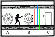
attachment.php

I screen capped it and drew on it...
175 F-C (Red)
225 F-F (Blue)
225 C-C (Green)
121 Woman (purple)
16 lower deck thickest
14 upper deck thinnest.

The woman is 0.691 X, the floor-to-ceiling is 1X, and floor to floor is 1.286X


If we assume a typical woman at 5'6" (1.67m), then knock off 10 cm for stance (1.57)... a little algebra and...
2.27m F-C
2.92m F-F

Not a match to the text.
Let's assume full height thanks to the heels:
2.415m F-C
3.105m F-F & C-C
Deck 19-22 cm thick

1.5x1.5x3.105 = 6.98625 m3
2x that is 13.9725 m3

I did the math with a very precise ruler and magnifying glass many years ago, and came up with 3.1m then, too.
 

Attachments

  • S7-P6-illo-annotated.gif
    S7-P6-illo-annotated.gif
    53.6 KB · Views: 45
Doesn't mean you couldn't make some access ways tighter and some rooms crampier.

You then can recruit from the shorter demographics of the population.
 
Doesn't mean you couldn't make some access ways tighter and some rooms crampier.

You then can recruit from the shorter demographics of the population.

Or recruit hivers and build 1.5 meter deck heights ... fitting 200 dtons of ship in a 100 dton hull. :)
 
Hello aramis,

First, I clicked on the quote button on your post aramis using both IE and Firefox in both browsers the reply pane opened without any material being quoted.

Next, thank you for supplying the CT LBB 2 Starships 1977/1980 or 2E and CT Supplement 7 1980 page numbers with the deck plan illustration and all the other work to determine the dimensions to fit 14 m^3 of LHyd.

My take on CT LBB 2 Starships 2E p. 13

"The Hull: Hulls are identified by their mass displacement, expressed in tons. As a rough guide, one ton equals 14 cubic meters (the volume of one ton of liquid hydrogen)."

is that a rough guide does not mean that the hull mass displacement of one ton is exactly equal to 14 m^3 or the volume of one ton of LHyd. My take was further reinforced by LBB 2 p. 21 and Supplement 7 p. 5 with the words of about and approximately.

Using the dimension information from both LBB 2 Starships 2E and Supplement 7 the volume I concluded by using 1.5 x 3 x 3 or 1.5 x 1.5 x 1.5 x 4 = 13.5 rounded up to fit the roughly 14 m^3 of LHyd to equal one mass displacement ton.

However, the design tables do support the use of 14 m^3 equaling one ton, which supports the idea that the about 3 m needed some clarification.

My methods are less ambitious than the one aramis used to figure out how many 1.5 x 1.5 x 3 squares I needed to hold 14 m^3 of LHyd which is approximately 2.0741 squares.

After I got a spreadsheet application using the dimensions of 1.5 x 1.5 x 3 from LBB 2 and did a goal seek analysis. The result of the calculation to get a volume of 14 m^3 required a height of approximately 6.2222 m. Starting with the dimensions of 1.5 x 3 x 3 the goal seek calculation changed the height to approximately 3.1111.

I have some PDF copies of MT and TNE books which does help a bit in looking up information. Unfortunately, I still have been unable to check the purchase of Traveller CD-ROMs off my wish list.

Thank you again for the reply.
 
Hello again warwizard,

Thank you for another reply.

Re the external armor, as the jump volume is everything from the outer skin in... I count the exterior armor as well.

Here is another example of rule interpretation that has kept design Traveller discussions going.

The CT rules, IIRC, do not mention that armor takes up volume that affects the jump drive inserting the ship into jump space. However, the rules do indicate that carrying external objects like drop tanks, which add their volume to the hull, alters the jump distance only if they are retained during the jump.

My interpretation based on the information, which may be out to lunch, is that CT armor does not affect a hulls internal volume.
 
Hello Condottiere and atpollard,

IIRC some of the alien modules made modifications to the original deck plans to take into account the differences if the body shapes of the various races.

If anyone has the CT CD they might be able to confirm, hopefully, that I'm not out in left field.
 
Hello again Condottiere,

The centaurs need a lot of space, I vaguely recall two or three times the volume listed.

I managed to did out my FFE reprints of the Alien Modules.

Traveller Alien Module 2 K'kree page 13 deck plan height is 6 meters rather than 3 meters and are flattened spheres which appears to be domed shape. Inside the hull there is 1 1/2 decks the main full deck is where the crew lives and works and the half deck is used for equipment and fuel. Other differences are standard hulls are given in 1,000 displacement ton increments and the interiors are generally one big space.

Looks like I was in error on the other seven modules after a quick look.
 
Hello again warwizard,

Thank you for another reply.


Here is another example of rule interpretation that has kept design Traveller discussions going.

The CT rules, IIRC, do not mention that armor takes up volume that affects the jump drive inserting the ship into jump space. However, the rules do indicate that carrying external objects like drop tanks, which add their volume to the hull, alters the jump distance only if they are retained during the jump.

My interpretation based on the information, which may be out to lunch, is that CT armor does not affect a hulls internal volume.

Thank you for the prompt response.

Well as this is the T4 discussion area, I was not going to bring in other editions into the discussion, but as this is your thread please feel free. CT and previously mentioned TNE tended to abstract armor and structure but Book 5 of CT did charge you 2% of volume per level of armor as I recall, so there is precedent in CT to account for additional armor beyond the basic hull, which was abstracted to take no volume, though one could argue the rather large bridge also accounted for the basic hull's material volume.

For T4 I have a ship designed at 100 Dt TL 8 hull that uses 26.51m3 for the hull volume which is a little less than 2 Dt, and that's with a configuration that nearly doubles the surface area, hence the material volume of the hull. so we're talking at most 2 Dt of a 100 ton hull or <2%. Of course as you scale up the % goes up due to internal bracing, as well as when you pile on the G's.
 
Evening PDT warwizard,

Oops, I forgot about LBB 5 since I answered a question about displacement tons earlier. Thank you for the correction.

Per Guy Garnett and David J. Golden T4 QSDS and SSDS used TNE FF&S. Further T4 tweaked TNE FF&S.

Unfortunately, I and many others do have a tendency to include the other Traveller rule sets. However, the biggest issue is the tangents that occur which is not that far off from the topic of jump drives yet, I think.

Thank you for the prompt response.

Well as this is the T4 discussion area, I was not going to bring in other editions into the discussion, but as this is your thread please feel free. CT and previously mentioned TNE tended to abstract armor and structure but Book 5 of CT did charge you 2% of volume per level of armor as I recall, so there is precedent in CT to account for additional armor beyond the basic hull, which was abstracted to take no volume, though one could argue the rather large bridge also accounted for the basic hull's material volume.

For T4 I have a ship designed at 100 Dt TL 8 hull that uses 26.51m3 for the hull volume which is a little less than 2 Dt, and that's with a configuration that nearly doubles the surface area, hence the material volume of the hull. so we're talking at most 2 Dt of a 100 ton hull or <2%. Of course as you scale up the % goes up due to internal bracing, as well as when you pile on the G's.

Personally I have small issues with the abstraction of what the bridge volume covers. I will agree that some of the total internal bracing is included in the bridge volume, but anything else goes with the other spaces of the ship.

Again thank you for your reply.
 
Back to the original posting, yes the way they wrote that section was just a result of restating everything per joules and m3 instead of MW and Dt.

The math works out pretty close I think the .2 of the 25.2 is due to using more precision in T4 FF&S. (I'm guilty of calculating to 5 decimal points as I use a spreadsheet with automatic formulas written into the cells whenever I can.)

We can discuss some interesting ship designs concepts I've had if you would like or we can start a new thread.

Gary
 
Hello warwizard,

My apologies for not replying earlier, unfortunately the area where I live lost power and I just got home to find the power restored.

Back to the original posting, yes the way they wrote that section was just a result of restating everything per joules and m3 instead of MW and Dt.

For the jump drive T4 FF&S added two tweaks not used in TNE FF&S design. The topic of this post was confirming that my understanding of

T4 Book B p. 12

"The amount of energy required to initiate a jump is equal to 64MJ per cubic meter per parsec jumped. This energy must be provided to the drive in an hour or less (meaning that a starship must have 0.018MW of power plant per cubic meter per jump number)."

"Once in jump space, the jump drive maintains a small bubble of real space around the ship, using power input to the jump drive from the power plant (0.018MW of power plant per cubic meter per jump number)."

I believe the above implies that a power plant installed on a 100 displacement ton (TD) hull capable of jumping 1 parsec must have a minimum output of 19.6 MW to provided the 89,600MJ of energy to initiate the jump.

I'm still not sure about being on the right track with the above.

The other difference is calculating statistics for a jump grid.

Since I've stalled in my T4 efforts I've been working on other stuff, but I'm sure there are other differences.

The math works out pretty close I think the .2 of the 25.2 is due to using more precision in T4 FF&S. (I'm guilty of calculating to 5 decimal points as I use a spreadsheet with automatic formulas written into the cells whenever I can.)

In my spreadsheets I usually round to four decimal places unless an example shows a different number of digits. While waiting for response on the TML posts I began working with a forum member trying to up date the combination spreadsheet Rb-98r4 found in the downloadable files section. Unfortunately, that died out because of differences of interpretation of the rules and rounding.

We can discuss some interesting ship designs concepts I've had if you would like or we can start a new thread.

Gary

If we do start discussing ship designs we should probably start a new thread and I'll try very hard not to get fixated on a tangent.
 
Back
Top