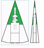
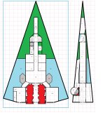
Ooh, pretty.
Not sure I can get the printer to do deck plans at the necessary resolution to fit onto a folded 8.5x11 sheet.
There's always 11 x 17.
Ooh, pretty.
Not sure I can get the printer to do deck plans at the necessary resolution to fit onto a folded 8.5x11 sheet.
Yeah.There's always 11 x 17.

Maybe. Or 16 as an "drive bay attic," plus a similar "basement". Pull the engine room bulkhead aft one row of squares to compensate, and use "bridge" tonnage to re-renable the transverse corridor.the engineering compartment consist of both locations 12 and 16
In a vacc suit?There is going to be a spot in the crawl-space just behind the iris valve that'll be wide enough for a person to turn around and start feet-first down the ladder in the main-deck hallway. Otherwise, it's 1m tall by 1.5m wide, ...
Makes sense, and has that industrial ambiance going for it.I picture the drive compartment being a box 6m total height, but its floor is 1.5m below the level of the main crew deck
Also -- and I think this mattered when they drew it up originally -- the habitable part of the deck plans (from the aft end to the forward-most part of the avionics crawlspace ahead of the cockpit) fits onto standard 8.5x11 paper!Speaking of oversized paper...
The main deck plan will fit onto a Legal (8.5" x 14") sheet inside the printable margins, when printed at 1/2"=1.5m scale.
I had to offset parts of the cockpit deck upward from the stateroom area, because the deck height of the seat platforms is set by the forward/outer corners of the compartment. Since it's not tall enough for easy access, the sides are raised from the centerline aisle. And the seats might not fit if they weren't tilted back slightly.The cockpit area is likewise a step down from the crew area.
if you do, pictures! I always love seeing how creative people are. And I have cardboard boxes...Sorry I should have read what I wrote - on my drawings the cockpit is indeed a step up, the crew deck is a step down.
I'm going to try building a scale model out of Amazon box cardboard.
Cereal boxes is probably a better source of cardboard for building, that corrugated stuff is a little big, but then it depends on how big you plan on making your model.I'm going to try building a scale model out of Amazon box cardboard.
Watching the time-lapse was was pretty cool. And the attention to detail is amazing! Sure, most of it is cardboard brown, but still...Cereal boxes is probably a better source of cardboard for building, that corrugated stuff is a little big, but then it depends on how big you plan on making your model.
The seats do fit. Might move them downwards slightly though for additional head-room, but it's not critical.I need to verify that, though! The seats might need to be even lower, with the leg-rests down at platform level instead of slightly raised. I copied them from the acceleration couches of one of my other designs, which were modeled after reclining chairs. Might need to go with literal "seats in a sports car" instead -- including the bit where the inside of the front wheel wells limit the occupant footwell dimensions.)

How about adding a shared Head in room #8?And here we go. Semi-final draft.
Numbered locations transferred from original with the following exceptions:
2a: This is the ship's Mod/1bis computer.
12: The drive room is 6m tall at the forward centerline. There is an expanded-metal grating deck at floor level, and an access hatch to the space under it. The drives are accessible from above and below, but there is little clearance. (Someone could hide in there...)
15: The Ship's Locker is an airtight compartment in the cargo hold. (Originally located forward of the Air/Raft.)
18: Turret and Drives Access Airlock (was Upper Gallery).
19: Was Forward Sensor Position and still is. It's also just a 1m tall x 1.5m wide crawl space. There is barely room for a person to turn around (sprawled flat to the deck) where the numbers are, and adjacent to the aft hatch. It is not possible to turn around elsewhere in the crawl space.
20: Main Personnel Airlock (was Forward Cargo Bay). Dorsal and ventral entry point. A ladder extends from the nose landing gear doors to facilitate entry from below. Airlock cycling/air purification equipment is adjacent.
View attachment 3832
Good idea. Also should have some dedicated food storage and prep space.How about adding a shared Head in room #8?
