• Welcome to the new COTI server. We've moved the Citizens to a new server. Please let us know in the COTI Website issue forum if you find any problems.
  • We, the systems administration staff, apologize for this unexpected outage of the boards. We have resolved the root cause of the problem and there should be no further disruptions.

Type S as a Tailsitter Prolate Spheroid

DECK PLANS RE-UPLOADED AT THE BOTTOM OF PREVIOUS PAGE. GO LOOK :)
The Air/Raft and Cargo Bay could easily be split, and an iris valve doorway provided to each side.

Staterooms feel a bit large (except for the half-stateroom in the bridge space) and probably ought to be downsized, with restroom facilities combined into a common bathroom or two.

And, as noted in the first post, the calculated hull volume is about 10% larger than 100Td; all components have been scaled up proportionately on the deck plans.
I "borrowed" some of the 20Td bridge volume allocation for hallways and the elevator.

It's a LBB2 '81 build.
 
Last edited:
DECK PLANS RE-UPLOADED AT THE BOTTOM OF PREVIOUS PAGE. GO LOOK :)
The Air/Raft and Cargo Bay could easily be split, and an iris valve doorway provided to each side.

Staterooms feel a bit large (except for the half-stateroom in the bridge space) and probably ought to be downsized, with restroom facilities combined into a common bathroom or two.

And, as noted in the first post, the calculated hull volume is about 10% larger than 100Td; all components have been scaled up proportionately on the deck plans.
I "borrowed" some of the 20Td bridge volume allocation for hallways and the elevator.

It's a LBB2 '81 build.
I'm working on fixing this a bit. Original plans on previous page: (cross-section) (deck plans)

Issues:
1. Low ceilings. I'd drawn them at about 2m (6'7")... US building code says 2.134m (7 feet) minimum with some exceptions. That works for a 97th-percentile male (2 sigma from median) with allowance for boot soles and headgear clearance, plus a small margin for vertical displacement during running. Standard used to be 2.44m (8 feet), but has moved toward 2.74m (9 feet) since the late 1970s. The drive room ceiling is less than 2m in height, and that definitely needs to be fixed (but not the "basement crawl-space" under it -- that's supposed to just hold one person, crouching).
2. Oversized staterooms. They're about 6 deck plan squares each but should probably be closer to 4 each, with the extra space going to common areas (probably including a common head, and definitely including food storage and preparation).
3. Splitting the 7Td cargo bay & air/raft garage into separate compartments. Combining them was an artistic decision, but I might un-do it to conform with canon since it's an easy fix.
4. A couple of minor drafting errors that I may not bother with.

Comments and/or suggestions?

Any other canon ships that you'd like to see in this kind of configuration?
 
2. Oversized staterooms. They're about 6 deck plan squares each but should probably be closer to 4 each, with the extra space going to common areas (probably including a common head, and definitely including food storage and preparation).
6 squares for staterooms goes all the way back to LBB S7, p16-17 ...
The staterooms (4, 5, 6, and 7) are large and spacious, an essential consideration when the crew may be forced to spend long hours together. The common area (8) contains recreation equipment, a galley, and eating facilities.
The fun part is that the 4x staterooms plus hallway plus common area consume 5x10 squares of the deck plan (or 25 tons of displacement!), while 16 tons of staterooms "ought to" only consume 32 squares (or 4x8 instead). I always just considered it a case of "spending some excess bridge tonnage" on the common areas and just moved on without a lot of hassle.
 
6 squares for staterooms goes all the way back to LBB S7, p16-17 ...

The fun part is that the 4x staterooms plus hallway plus common area consume 5x10 squares of the deck plan (or 25 tons of displacement!), while 16 tons of staterooms "ought to" only consume 32 squares (or 4x8 instead). I always just considered it a case of "spending some excess bridge tonnage" on the common areas and just moved on without a lot of hassle.
In this particular design, the hull is 10% larger than the nominal displacement, so each individual component gets scaled up likewise (drafting error margin). Also, there's some fuel tank (the scoops) tonnage, some explicitly bridge tonnage (the green boxes), and some implicit bridge tonnage (elevator) on this deck.

Large staterooms with smaller shared spaces were common in early designs; later ones tend toward smaller staterooms and larger shared spaces.
 
The two hull sizes that will probably meet the most need are the 200t and 400t, so you could do those next, please :)

I picture a tail-sitting trader as having a very wide base so that all the cargo goes on the floor closest to the ground, with the m-drive pods on this level too.
 
The two hull sizes that will probably meet the most need are the 200t and 400t, so you could do those next, please :)

I picture a tail-sitting trader as having a very wide base so that all the cargo goes on the floor closest to the ground, with the m-drive pods on this level too.
Decent idea, and an inspiration: I hadn't thought about putting the drives above the cargo hold, but with sufficient aft hull taper you could have the exhaust go around/past the tail (also, using outboard motors...)
 
So ... something akin to this ...?

It's not rendering properly in my browser, alas.

EDIT: It works in the reply preview. Probably works if I refresh the page...

EDIT 2: Yep. That was weird.

EDIT 3: So, an aerospike engine but only for braking/steering in the EDL phase. Interesting.
 
Last edited:
tumblr_inline_nyqyak29CR1r0nx58_1280.jpg


Wide enough base.
 
Revised Deck Plans
Changes:
- Longitudinal Section View now has 2.13m (7 foot) ceilings where appropriate.
- Deck Plans now has the Air/Raft in a dedicated bay, separate from the cargo bay.

Overview
(Mostly copied from post #1 of this thread, edited as appropriate.)

The hull is a 2:1 (length:equatorial diameter) prolate spheroid, 22.5m x 11.25m.
This comes out to about 110Td excluding the turret -- close enough.

The longitudinal section highlights the elevator and flight deck access pathway, at the expense of not showing the fuel scoops or the layout of the Jump Drive. The former are the open rectangles on the periphery of decks 2-3, leading to the fuel processors (which aren't needed under LBB2, but I'm putting them there anyhow) on deck 4. The latter are two cylinders extending through the drive deck and projecting upwards 2m into the fuel tank area -- this can be seen in the sectional view, but only in outline.

I may do an additional illustration of the top and bottom end-views to clarify those, but that's for later.

Deck 1, Deck 5, and the "cellar" under Deck 5 are each 2m tall, not the standard 3m.
The fuel tank's deck plan is omitted partly because of its lethal temperature and pressure, but mostly because there's not enough room on the "paper".

The heavy-weighted hull outline is each deck's mean diameter. The lighter outer circle is either the diameter at the floor of decks tapering toward the top, or at the ceiling of decks tapering toward the bottom.
"Sparse" electronics and machinery spaces have passages through them, but hinder movement severely.
"Inert machinery" is just heavy machinery that doesn't get all explodey when you shoot at it.

If printed full-size, it ought to be scaled correctly for Snapshot and AHL combat rules.
(The grid squares are 1/2", representing 1.5m in those systems.)

Longitudinal Section:
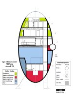
S as TS talldecks.jpg

Transverse Sections (a.k.a. deck plans):

Note: Fuel tank zone not depicted.
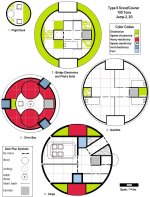
SDecksRev1.jpg


Details:

1. Flight Deck: There are two acceleration couches. The ceiling of this deck is a transparent parabolic dome; its peak is 2.25m above the deck. The floor hatch leads to the ladder shaft from the Pilot's Suite deck. There is no inter-deck space between this deck and the next, only a bulkhead.
Spoiler:
The clear dome is only there because people expect a cockpit to have windows. A more practical design would have sensors in the nose, and relocate the flight control station into the next deck down.

The "nose" section (stations 0m to 2.25m) is 1.8Td (2Td calculated volume). Here, as on all decks, the calculated volume is 10% larger than the components contained on the deck. This is because the prolate spheroid of the hull is 110Td in volume, not 100Td exactly.

2. Bridge Electronics and Pilot's Suite: There is one half-stateroom, with a bunk on one side of the hallway and a compact washroom and closet on the other. Sliding panels can enclose the bed space for privacy.

The open rectangular spaces at the deck perimeter at the 6- and 12-o'clock positions are intakes for the fuel scoops. The scoops and associated machinery extend downward through the next two decks.

The ladder shaft up to the Flight Deck can serve as an airlock between the two decks if necessary.

Each level of the elevator shaft can serve as an airlock between decks, as there are airtight hatches in the shaft between each deck.
The elevator has emergency access hatches in its floor and ceiling, so a stuck elevator does not prevent access between decks. It also has UV sterilizing lights (with a safety interlock) and high-efficiency air filters for use when the elevator car becomes the dirt-side airlock by extending the elevator shaft down to ground level through the bottom cuve of the hull.
Spoiler:
This deck is my answer to the problem presented by the canon Type S: it's not safe to carry paying passengers, as the pilot's quarters and path to the bridge aren't defensible against a hijacking attempt. I solved it here by having the pilot live "on" the bridge.

The fuel scoop volume is allocated against fuel tank tonnage. The pilot's suite is 2Td of stateroom volume, plus 1Td of bridge volume for the walkway between the bunk and the washroom/storage space.

This section of the hull (stations 2.25m to 5.25m) is 11.7Td (13Td calculated volume).

3. Quarters Deck: There are three staterooms and an open lounge on this deck, as well as ducting and machinery for the fuel scoops and some electrical conduits.
Spoiler:
The fuel scoop volume is allocated against fuel tank tonnage. The electrical conduits and elevator are allocated against bridge tonnage.

This section of the hull (stations 5.25 to 8.25m) is 17.1Td (19Td calculated volume).

4. Cargo Deck: There is a 4Td bay for the ship's Air/Raft, and a 3Td cargo bay. There are also a personnel airlock, the ship's locker, and access to the ship's turret from the space outboard of the elevator. The processing machinery of the fuel scoops is also on this deck.

The cargo bay has a retractable winch gantry rated at 6000kg.

There are wall brackets for pre-staging ordnance next to the turret access iris valve, to facilitate reloading during combat.

The "sparse machinery" around the personnel airlock includes the airlock docking coupler (retracted) and air tanks, compressors, and filters/sterilizers for cycling the airlock.
Spoiler:

LBB2 doesn't require any space to be allocated for fuel processing by military/scout vessels. The scoops and machinery are just a pretext to bring some "fuel tank" tonnage up past the hull's equator. That, and I think they make a nice counterpoint to the huge Jump Drive exhaust nozzles, which we'll get to in a bit. The ship's locker and some of the hallway space are drawn from the bridge allocation.

This section of the hull (stations 8.25m to 11.25m) is 19.8Td (22Td calculated volume).

[Not numbered] Fuel Tank: This deck is 8.25m tall. The 3 landing gear wells (1.5m square by 2m tall on this deck, conformal to the curve of the hull) extend up into this space at the 1-, 5-, and 9-o'clock positions. The top of the Jump Drive extends into this space as two cylinders 3m in diameter by 2m tall, located above the 3m diameter circles on the Drive Bay deck plan. The elevator passes through this space as a 1.5m square pillar at the 3-o'clock position, 2.25m from the center of the deck. The lower half of the turret projects 1.5m into this space from the ceiling.
Spoiler:
This section of the hull (stations 11.25m to 17.5m) is 6.25m tall, and is 35Td (36.5Td calcuated volume).
The jump drive extensions into this space are because I used a couple of Td of the drive bay for the elevator and landing gear wells.

I'll probably do a sketch of the fuel tank to show what I did. It's a kind of complicated visually, made worse because I'm drawing in MS Paint...

I didn't do deck plans for it because nobody should be in there in the first place. Well, that and there wasn't room on the "sheet of paper" for it... LOL

5. Drive Bay: There is an acceleration couch and control console. The two 3m dia. circles of heavy machinery are the Jump Drive. They are cylindrical and extend upwards into the fuel tank by 2m, and down to the curve of the hull in the space below this deck. The floor hatch provides access to a roughly 1.5m square by 2m tall maintenance niche below. The three 1.5m squares at the deck periphery are the landing gear wells; they extend 2m upwards into the fuel tank space.

The elevator tube can be extended downward through the hull (through a hull door at about the level of the maintenance niche below this deck) to ground level.

There is no inter-deck space between this deck and the fuel tank, nor in the space between this deck and the maintenance access space below it.
Spoiler:
This section of the hull (stations 17.5m to 28.5m) is 15Td (16.5Td calculated volume).
 
Last edited:
I like the pilot stateroom less for security and more for the courier pilot only role for x boat auxiliary work- quick to the bridge in an emergency.
 
What tool/app did you use to create the new deck plans?
Same as always, nothing but the most-sophisticated tools: MS Paint. It shows most noticeably in the landing gear wells, because Paint doesn't do measured angles and I had to improvise to make the 60 degree angles. The other issue is that it doesn't have a native greyscale fill, so I approximated with the spray-can tool.
 
Back
Top