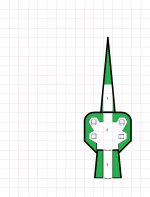
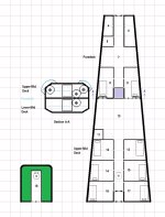
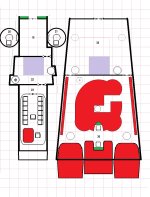
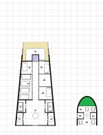
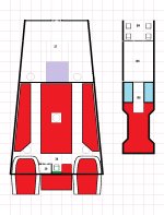
This is a month-long project (see COTI thread Fixing the Type T Deck Plans?) provoked by the discovery that the deck plans provided in FASA's Adventure Class Ships, Vol. II for the Type T Patrol Cruiser did not match the illustration on the cover of the box. Not only that, but also they didn't match the description of the Type T Patrol Cruiser given in LBB2 '81, p. 20. Further, the plans themselves, while satisfactory for most situations in which player characters would interact with a ship of that class, do not represent a usable layout for the hypothetical crew working aboard it – for example, they lack common spaces such as wardrooms and galleys.
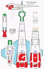
What follows is my interpretation of that cover illustration.[SPOILER="Draftsman's Notes"]
It's likely quite similar to the deck plans upon which that illustration was based, with a few minor changes. The first is that I've provided individual cabins for each flight crew member including the gunners (who are double-bunked in the LBB2 description, and almost certainly were on those plans as well) while retaining the same overall crew space (40Td, or 10 stateroom-equivalents) for those personnel. The second is that I've interpreted the layout as being a split-level design, with the flight deck and foredeck at a level halfway between the upper and lower mid/aft decks. (In the original plans, the foredeck's vertical offset might have involved stairs or stair-step floor height changes rather than an elevator.) The third change is that I've moved the Low Passage Berths from behind the flight deck to the aft end of the ship's troops' barracks on the lower deck.
Notably, the ACS Vol. II deck plans moved the Ship's Boat from underslung external grapples into the clamshell bay at the aft end of the top deck, and the GCarrier from that clamshell bay to one just forward of it. These revised plans have reversed those re-locations.
[/SPOILER]
Except for the lateral section view, the plans are in 0.25"=1.5m scale. The lateral section view is half-sized (0.25"=3m).
Subsequent plan elements in this thread are natively* 0.5"=1.5m (suitable for 28mm figures when printed out at full size, and each section can be printed on 8.5"x11" paper within the printable area of the sheet).
------------------
*Right-click and open image in new page, then save the image from there.
What follows is my interpretation of that cover illustration.[SPOILER="Draftsman's Notes"]
It's likely quite similar to the deck plans upon which that illustration was based, with a few minor changes. The first is that I've provided individual cabins for each flight crew member including the gunners (who are double-bunked in the LBB2 description, and almost certainly were on those plans as well) while retaining the same overall crew space (40Td, or 10 stateroom-equivalents) for those personnel. The second is that I've interpreted the layout as being a split-level design, with the flight deck and foredeck at a level halfway between the upper and lower mid/aft decks. (In the original plans, the foredeck's vertical offset might have involved stairs or stair-step floor height changes rather than an elevator.) The third change is that I've moved the Low Passage Berths from behind the flight deck to the aft end of the ship's troops' barracks on the lower deck.
Notably, the ACS Vol. II deck plans moved the Ship's Boat from underslung external grapples into the clamshell bay at the aft end of the top deck, and the GCarrier from that clamshell bay to one just forward of it. These revised plans have reversed those re-locations.
[/SPOILER]
Except for the lateral section view, the plans are in 0.25"=1.5m scale. The lateral section view is half-sized (0.25"=3m).
Subsequent plan elements in this thread are natively* 0.5"=1.5m (suitable for 28mm figures when printed out at full size, and each section can be printed on 8.5"x11" paper within the printable area of the sheet).

------------------
*Right-click and open image in new page, then save the image from there.

