• Welcome to the new COTI server. We've moved the Citizens to a new server. Please let us know in the COTI Website issue forum if you find any problems.

CT Only: Fixing the Type T Deck Plans?

Grav_Moped

SOC-14 5K
Admin Award 2022
Knight
I like the looks of the FASA Type T (ACS Ships, Vol II), but those deck plans need some love. Three staterooms worth of living quarters are just plain missing, there's no common space for the crew, and what in the heck are the low berths doing up by the bridge? This isn't a ship you'd spend weeks aboard while out on patrol, to say the least. And I'm not sold on the "wedgy" Ship's Boat design. If it's not a needle configuration (as with other canon small craft), it should share design features with its parent ship.

And the whole thing looks like it was squished longitudinally so it would fit onto the paper (which no doubt it was), compared with the artwork.

The Corvette plans that came with the T5.1 kickstarter have similar issues, but they're reflecting a slightly different ship built under T5 rules so I can't really fault them for it.

More to follow.
 

Attachments

  • Type T.JPG
    Type T.JPG
    108.3 KB · Views: 217
  • Type T Decks.JPG
    Type T Decks.JPG
    166.5 KB · Views: 106
I'm up for this interesting challenge.

First up, which art most represents the Type-T? So many good one to choose from.

Then determining the outline and scale.

iu-1.jpegtype-t-under-fire.png

1_400dtPC_PICTURE_000.jpg 1_LurusharKilaluumCollage2.jpg
 
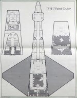
Doing a more thorough inspection of the plans ... it looks like someone chose the dimensions first (length, beam, etc.) and then started filling in with "stuff" and wound up with not enough space to fit everything.

The cargo bay split across 2 decks amounts to all of ~70 squares of deck space, which is 35 tons, not 50 tons.

Per LBB2.81, the F/H/H drives ought to be 35 tons jump, 15 tons maneuver and 25 tons power plant (total: 75 tons).
The maneuver drive + power plant on the main deck barely exceeds 70 deck squares (35 tons) even when including the corridors ... so it's close to being the right size but doesn't quite manage to be large enough.
The jump drive on the lower deck occupies ~70 squares also (35 tons) so it's pretty close to being right.

The overall length of the main deck is 42 deck squares (63m) from nose to stern, but it should probably be more like 50 deck squares (75m) so everything can fit in properly.

Those wing tanks are obviously too small to be holding 160 tons (320 deck squares) worth of fuel.

If I zoom way in on the image to measure those wing tanks, to the point where each deck square is 33x33 pixels on my screen ... if I measure the wing tanks I get a 390x265 pixels forward, 390x66 pixels mid section and 382x266 aft section. Converting those pixel counts to deck squares, I get 11.8x8 triangle, 11.8x2 rectangle, 11.5x8 triangle. Using 1/2bh for triangle area of the two triangles in the trapezoidal wings ... I get 47.2, 23.6 and 46 deck squares respectively, for a total of 116.8 (call it 117) deck squares (58.5 tons) of fuel per wing or 117 tons of fuel total between the two wings. That's about right for the original (not yet errata corrected) amount of 120 tons listed in LBB2.81 but obviously wrong for the errata corrected amount of 160 tons of fuel.

In other words, the wings need to get bigger.

Giving the main hull a 3/5/7 deck squares wide cross section for the hull forward of the wings makes a lot of sense, since it gives you a single central corridor with 1, 2 or 3 deck squares of space on either side to work with for habitation. So the width/beam of the hull doesn't need to change all that much, but the longitudinal length ought to be increased. 42 deck squares long is simply NOT enough space to work with.

The deck plans do need a significant tweak to them, but not necessarily a radical redesign.
Putting the only egress points for the entire ship via airlock over the wings, however, does look like a mistake ... :cautious:

So yeah ... a redesign to "get it right" would seem to be in order, but there's definitely enough fiddling around that needs to be done that you're better off starting with a clean sheet of (graph) paper and working your way up starting with the required interior dimensions for things to make sure that everything fits.
First up, which art most represents the Type-T?
No contest.
@magmagmag does the definitively best art work. I would start from there.
 
The jump drive on the lower deck occupies ~70 squares also (35 tons) so it's pretty close to being right.
This is one area that I generally under represent. I figure that some of the tonnage of a jump drive is taken up with the jump grid on the exterior hull. No general rule, but I'd probably draw the jump drives in the 25 to 30 square range.
 
The funny thing though is that many of those images are "scaleless".

The last two certainly have something of reference, notably an airlock, perhaps the cockpit bubbles. The last one has an air raft with a person in it.

The first two, however, at best, have the turrets as a scale reference. But those could be 16" guns off the New Jersey!

So, there's room to stretch the ship to better accommodate the crew and the mission without everything going haywire.
 
Those gigantic winglets on the ends of the wings are probably there to help with heat dissipation by radiation. More surface area to radiate away waste heat.
 
If it's (at a guess) 10 units long, 2 units wide, and 1 unit high, that's ~3.33 cubic units corresponding to 5600 m3, or 1680 m3 per cubic unit, hence a unit is the cube root of that or about 12 m.

That would make the hull 120 m long, 24 m wide, and 12 m high (at the base). That's a bit over tonnage, but within customary limits; the wings might strain the limits.

Well that's a rough estimate to start with...
 
Those gigantic winglets on the ends of the wings are probably there to help with heat dissipation by radiation. More surface area to radiate away waste heat.
If so, they're part of the power plant and/or jump drive tonnage. That implies heat conductors from the drives, though.

They could also (or instead) be bridge tonnage, containing sensors and antennae.
 
In other words, the wings need to get bigger.
Aside from the tank size errata, there could be fuel wrapped around the upper and lower decks for contouring. Not sure I buy that, but it's not impossible.
Putting the only egress points for the entire ship via airlock over the wings, however, does look like a mistake ...
Yeah. It also suggests the wings aren't a full 3m thick at that point, which they'd almost have to be to contain the required fuel.
 
If it's (at a guess) 10 units long, 2 units wide, and 1 unit high, that's ~3.33 cubic units corresponding to 5600 m3, or 1680 m3 per cubic unit, hence a unit is the cube root of that or about 12 m.

That would make the hull 120 m long, 24 m wide, and 12 m high (at the base). That's a bit over tonnage, but within customary limits; the wings might strain the limits.

Well that's a rough estimate to start with...
Quite useful! The wings can be whatever thickness is needed to compensate for other items, and fuel space can be displaced into the main hull.
 
I think I might have cracked why the published design provided is only 41 deck squares long. :unsure:

So I broke out a pad of 8.5x11 graph paper with the blue squares on it. You know, basically this kind of stuff.
d3ff776b-50e4-4753-9c4e-5b0900c7c763_1.9f56b02e631b51dcf7248bb7225e41af.jpeg

And what did I find when I counted the 5mm squares?
Left to right = 33 available squares usable area
Top to bottom = 43 available squares usable area

The published deck plans are 31 squares wide from wingtip to wingtip ... and 41 squares from nose to stern.
Just barely what you can fit onto a single page of graph paper.

In other words, the circumstantial evidence STRONGLY suggests that the published deck plan was roughed out on 5mm grid 8.5x11 paper before being assembled into a format suitable for publishing. I submit that THAT simple logistical correlation cannot be a coincidence.

So ... if the hull size is "too small" to make everything fit the way it's all supposed to ... what about making the main hull wider rather than longer?

Instead of the forward fusalage being 3 deck squares wide at its narrowest point behind the bridge, what about making it 5 deck squares wide behind the bridge, and letting the bridge "squoosh outwards" to being 7 deck squares wide but shorter fore to aft? You then still have the taper from 5 to 1 for the computer and avionics forward of the bridge.

With a wider fuselage aft of the bridge, you can orient the staterooms along the central corridor in a 3x2 "wide" arrangement outboard, rather than in a 2x3 "long" arrangement longitudinal like we see in the published plans.

Stretch the wings a bit more forward to increase the fuel tankage and you're on your way.

Hmmm ... I might need to draw up some plans using my meager tools to illustrate what I'm talking about here. :unsure:
 
This is the rough outline I have come up with. If drawn on 1/5 per inch graph paper it would be 12.4" long and 8" wide. Too big for a piece of paper. But, we're in the digital age of scaling as needed. In terms of squares, it comes out at 647 on the main level, 794 with an upper deck added. (I didn't count the extra in the eye balls :rolleyes:) so right were I want to be for a 400t Type-T Patrol Cruiser.

Deckplan Grid.png
 
Out of curiousity, what tool did you use for your outline? Notably, how did you fill it with squares.
AutoCAD LT 2020.

I drew the grid on a layer. I extend and trim the grid to fit the outline. It really wasn't that hard this time. I just started with another deckplan and copied and pasted. I have predrawn staterooms, chairs, Air/Rafts, etc. that I have created over the years that I can just drop in.
 
Okay, here's a convenient resource for drawing deck plans onto that I've built.

Graph Paper png image (imgur hosted) 1280x1264 @ 72 dpi
1 square of deck space is effectively 30x30 pixels.
42 squares wide x 43 squares high of usable deck area.

So if you have a ship that "wants to be" an odd number of squares wide (so you can do 3+1+3, for example with a central corridor) you can orient the ship fore/aft on the left to right axis in the middle. If your ship "wants to be" an even number of squares wide (so you can do 3+2+3, for example with a wider central corridor) you can orient the ship fore/aft on the top to bottom axis in the middle.

This way, you have a common reference image that can handle both even and odd number balances of symmetry without triggering OCD attacks (hey, it happens to the best of us ... :rolleyes:).

With the basic graph paper problem sorted out, I (and anyone else) can use simple line drawing software to mark up the paper (I'm limited to OSX Preview as my drawing tool for this kind of thing).


Now ... what kind of mischief can I get up to with this graph paper reference material to draw on ... :unsure:

Honestly, these days I would really want to give the Type-T more of a Cranked Arrow wing planform. than the legacy drawings (which were done before the F-16XL testing program first flight in 1982).
240px-Wing_cranked_arrow.svg.png

A cranked arrow wing planform would help move the center of lift forward, better balancing the center of lift and the center of mass while also being "friendlier" in aerodynamics to supersonic flight. Yes, with gravitic/maneuver drives that's less of an issue, but if the wings are going to be there at all, might as well make them less problematic to the overall engineering ... right?

Of course, at that point, you're undertaking a more comprehensive redesign of the Type-T ... but I'm not averse to such a move if the deck plans need a refresh anyway.
 
In terms of squares, it comes out at 647 on the main level, 794 with an upper deck added. (I didn't count the extra in the eye balls :rolleyes:) so right were I want to be for a 400t Type-T Patrol Cruiser.
That works, but the disadvantage is that you force the hull to conform to the deck. The ship now has to be exactly 3 m thick, or exactly 6 m thick with the extra floor. That would give it a boxy, clunky appearance.

I prefer to draw a hull shape, then fit the decks into the hull. There's generally a lot of wasted space, but that's what the fuel tanks are for...
 
I'm thinking something like this:

A sideways pyramid with an elliptical cross-section:
The hull is 12 m high, 24 m wide, and 120 m long.
We can see how the decks fit into the hull, and that the deck volume is much smaller than hull volume.

Skärmavbild 2022-04-06 kl. 23.42.png
You can of course make the rear boxier and the front taper less with a truncated tip, to look a bit more like some of the exterior illustrations.
 
Deck A & C are triangles ~17.5 m × 40 m = 350 m2 ≈ 155 squares ≈ 78 Dt each.
Deck B is a triangle ~23 m × 90 m = 1035 m2 ≈ 460 squares ≈ 230 Dt.
Total 386 Dt, oops, I made the hull too big by making the cross section elliptical instead of rhomboid.

Time to downsize a bit, but you get the drift...
 
Deck A & C are triangles ~17.5 m × 40 m = 350 m2 ≈ 155 squares ≈ 78 Dt each.
Deck B is a triangle ~23 m × 90 m = 1035 m2 ≈ 460 squares ≈ 230 Dt.
Total 386 Dt, oops, I made the hull too big by making the cross section elliptical instead of rhomboid.

Time to downsize a bit, but you get the drift...
Leaves 14Td for the wings, before the 20% margin (80Td) of error. And since you're using contained prisms for the decks instead of conic sections, it's possible to stuff fuel into the nooks and crannies. Yeah, probably not, but it's closer than you think. Good enough for back-of-envelope calculations.
 
Back
Top