• Welcome to the new COTI server. We've moved the Citizens to a new server. Please let us know in the COTI Website issue forum if you find any problems.

CT Only: Fixing the Type T Deck Plans?

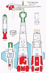
I'm thinking this is viable (ETA: my composition demo at the bottom of the previous page of this thread).

Side cutaway is layered over the nose (non-transparent, with some whitespace margin where it overlaps).

Also, the side cutaway could/should have the ship's boat with its deck parallel to those of the parent ship, with the sliding door on the far side in outline.

This "poster" is still natively 1/4"=1.5m, except for the side view which is now 1/8"=1m and thus outright rubbish...
 
Last edited:
So, any format suggestions?

It needs to at least work on the forum on a fair-sized monitor.

Ideally, it should be printable as a pdf at 1/2"=1.5m, along with pages of the room descriptions and details (size to be determined).
 
The side view has terrible artifacting from being downsized 50% -- just putting this up to see if the composition works out functionally.
For future projects consider using a "draw" (vector-based) software, rather than a "paint" (pixel-based) software. It's easier to change things around, and scaling does not matter.
 
The other 95% of the worlds population does not use "standard" or "legal", but A4. Leave a little wriggle room, and avoid legal?

If you want to print it on several pages, just leave a some margins and let the user do a little manual cut-and-paste?
It'd definitely fit on an A1 sheet (23 2/8" x 33 1/8"). North American (ANSI/ASME Y14.1) sizes would require ANSI D (22" x 34") sheets, and I'm not sure how common that (or the ability to print it) is.

Yeah, the only requirement for a legal-size sheet is to get the whole thing onto one sheet at "half-size" (1/4"=1.5m). At "full scale" (1/2"=1.5m), it won't fit on Tabloid (11" x 17") sheets -- which is the problem that started this whole mess back in the '80s!

But I think it does need a full-layout on a single sheet somewhere in the package.
For future projects consider using a "draw" (vector-based) software, rather than a "paint" (pixel-based) software. It's easier to change things around, and scaling does not matter.
Might keep the file size down too, for what that's worth (it'll end up as a jpg anyhow, and probably embedded in a pdf).
 
Last edited:
And I'm pondering the "art style" to use. Right now, I'm modeling it after the Azhanti High Lightning color key, and drawing plausible machinery outlines. On the other hand, it's tempting to mimic the original monochrome color scheme* and jagged-but-rectilinear machinery outlines....

I think I'll save the "retro-look" for the reconstructed-original version (what I think the original deck plan would have been) and do AHL-style for my updated version (what I think the deck plan should be while still conforming to the illustration).

------------------------
*with the slight problem that MS Paint doesn't actually have a monochrome halftone "fill" and I'd have to create it manually -- not impossible, but tedious.
 
Might keep the file size down too, for what that's worth (it'll end up as a jpg anyhow, and probably embedded in a pdf).
No need to make it a jpeg, ever. PDF is quite capable of handling vector graphics, so e.g. scalable and copyable text:
 

Attachments

  • Type T deckplan.pdf
    476.1 KB · Views: 9
No need to make it a jpeg, ever.
He's using Paint, there are no vectors. Now, that said, JPEG is not the best format for a bit map image (especially one with as much contrast as a deckplan), but PDF wouldn't help. It all depends on the internal bitmap format shoved in the PDF.
 
No need to make it a jpeg, ever. PDF is quite capable of handling vector graphics, so e.g. scalable and copyable text:
He's using Paint, there are no vectors. Now, that said, JPEG is not the best format for a bit map image (especially one with as much contrast as a deckplan), but PDF wouldn't help. It all depends on the internal bitmap format shoved in the PDF.
I was assuming the constraint was the forum's upload file type limits -- it doesn't take *.bmp, at least. Can't say I blame them.
 
Last edited:
Nose Section (flight deck, computer, storage lockers, toilet for the bridge crew) in 1/2"=1.5m. Pretty much final, posted here as an example. The symbols key will probably go here on the final version. It's 8"x10.5", so it should print full-size on Letter (8.5"x11") sheets without running into anyone's printer's margin limits.

It's offset because the foredeck/upper-mid-deck will be sharing space with the attic (to its left) as the plans proceed aft, aligned horizontally.

The ship's boat will share space with the lower deck (to the right of the lower deck), also aligned horizontally.

Once I get the whole thing done in 1/2"=1.5m and cleaned up, I'll dump all of it into a new thread with a writeup.
FS Nose.jpg
 
Last edited:
Status update:

Still plugging away.

Writeups for flight deck, fore and upper-aft crew quarters, and attic complete.
1/2"=1.5m sectional plans for attic, ship's boat, and everything from the cargo hold forward complete.

Managed to botch the large-scale drive bay/cargo hold drawings (spliced in an extra 3m lengthwise that shouldn't be there, on both decks!) and need to re-do them.
 
Last edited:
Final status update and a link in case someone eventually runs across this thread and wonders what came of it.

It's done, and posted a couple of days ago.

Type T Deckplans, Fixed

Again, thanks to everyone for their feedback and interest.
 
Back
Top