• Welcome to the new COTI server. We've moved the Citizens to a new server. Please let us know in the COTI Website issue forum if you find any problems.
  • We, the systems administration staff, apologize for this unexpected outage of the boards. We have resolved the root cause of the problem and there should be no further disruptions.

Type ST Transport Scout: 199Td, J4/2G (LBB2 2nd Ed.)

If I recall correctly, you have a twenty tonne bridge, so plenty of space
There's room for bridge equipment -- that isn't the problem. The problem is that the cockpit is up in the pointy end where there isn't much elbow room around where the seats got placed.

[Edit to add: that's the basic problem here: it's not that there isn't enough room "on paper," it's that the deck plans show things placed where they geometrically cannot fit inside the hull as drawn.]

I don't want to go to isometric drawings (I'm working in Paint which does not support defined angles so I'll have to math it out) but I might have to.
 
Last edited:
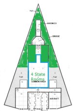
Let's go back to the basic assumptions. 4 staterooms is 16td of living space, which at the full 3m height is 32 each 1.5m squares.

The quarters section is 5 squares wide, so the living space should be 6 squares long, plus two more squares.

<looks at the 25 deck squares used for the common area ahead of the drive bay and transverse corridor>

<looks at notes: yep, needs only 32 total. Maybe less, since the hull is undersized>

<laughs, with the laughter becoming hysterically deranged>
Scribble S 1 jpg.jpg
 
Last edited:
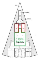
Ok, the red area isn't actually a whole lot of volume.

On the other hand, it's not particularly useful as staterooms either because there's not enough room (height, mostly).
 
Now, trying to figure out the bridge volume.
Calculating the volume of the pyramid that includes the back edge of the cockpit (15m from nose): 5.74Td (77.55m^3).

Did I mention that it's a skinny pointy bit out there?

How far back do I need to go to get 20Td? 22.5 m aft of the nose yields 19.38Td (but count it as 15% more since the hull's undersized so it's 22.8Td of on-paper components.)

That line happens about 1 row of squares behind the Big Block of Stateroom Space.

Edit: missed a spot. Fixed, because I care. :P
Scribble S 1 jpg.jpg
 
Let's go back to the basic assumptions. 4 staterooms is 16td of living space, which at the full 3m height is 32 each 1.5m squares.
This is the kind of basic computation that I'm doing with my deck plans.
First I figure out the aggregate of how much tonnage I need to account for, multiply that by 14 to calculate the m3 I need to be working with. From there I divide by 3 (deck height) and by 1.5 and 1.5 again (single deck square) and that tells me how many deck squares I ought to allocate for that amount of tonnage.
  • 12 tons * 14 / 3 / 1.5 / 1.5 = 24.89 = 25 squares = 5x5
  • 16 tons * 14 / 3 / 1.5 / 1.5 = 33.18 = 33 squares = 11x3
  • 20 tons * 14 / 3 / 1.5 / 1.5 = 41.48 = 41 squares
  • 60 tons * 14 / 3 / 1.5 / 1.5 = 124.44 = 124 squares
So if your 100 ton Scout/Courier devotes 40 tons to fuel (go figure... :rolleyes:) that then ipso facto means that 100-40=60 tons remains for interior spaces, which in turn means that there ought to be 124 squares devoted to deck area inside the hull when using 3m high decks (of which 2.5m are habitable interior space, with the remaining 0.5m used for services routing).

After that, it's just a matter of "counting up the squares" to make sure you're approximately right. This is where "using excess bridge volume" to allocate into corridors and the like (not just a cockpit and avionics) starts making sense.

This is basically what I've been doing with my Deck Plans research lately as a way to "proof" my arrangements when laying stuff out and trying to decide where the outer bulkheads on the hull go, followed by dividing up the internal spaces with yet more bulkheads and partitions. A lot of the time, I try to rough out where the furnishings/machinery is going to need to be and then use that as my guideline for how to "shape" rooms that can fit around their contents. Adding curves, triangles and trapezoids to the hull silhouette shapes makes this "just count the squares, stupid!" task a little more challenging (depending on how ridiculous you want to get with them), but it's still just basic geometry to count up the squares ... even if I have to do it piecemeal in chunks. It's just a matter of adding it all up.

So something as simple as trying to figure out "how big should the drive bay be?" becomes a much more manageable problem.
  • A/A/A drives = 10+1+4 = 15 tons * 14 / 3 / 1.5 / 1.5 = 31.11 = 31 squares
Note that those 31 squares ought to include the "boundary lines" of the room itself plus any corridor access to reach the drive bay itself, so as to connect things to the rest of the ship ... unless you "bill" the connecting corridor to the the bridge tonnage instead.

This is where making staterooms face each other across a common corridor running between them starts becoming a lot more space efficient.
A 3x2 stateroom all by itself with a corridor outside that it doesn't share with anything else actually costs either 3x3 squares or 2x4 squares, depending on orientation of the stateroom relative to the corridor (long side or short side common wall), which is obviously either 9 or 8 squares per stateroom along a single purpose corridor. But if you've got staterooms flanking a common corridor running between them, those 3x2 staterooms become either 3x2.5 or 2x4.5 each, with is then either 7.5 or 9 squares per stateroom due to the "sharing" of the corridor between them.

As I've demonstrated in my Deck Plans research you can make individual staterooms as small as 2.5x2 (5 squares) and put them facing each other along common corridors (so 12.5 squares for 2 staterooms) in order to have enough "leftover space" for the creation of common lounge and services areas. That way you can have 3 staterooms allocated (12 tons) and still get 4 actual rooms, accommodating 3 persons with the 4th room being a common area shared between the 3 persons.
 
Edited image in post #186

Because I care. :p

And I can kind of see why they did what they did. Doing it correctly looks wrong if it's not clear that the ship is a very flat pyramid/arrowhead shape. And from just a set of deck plans, that's very much not clear.
 
This is where "using excess bridge volume" to allocate into corridors and the like (not just a cockpit and avionics) starts making sense.
Indeed. That transverse corridor ahead of the drive room? Bridge. Move the back edge of the "bridge block" forward one square.

Move it forward another square and that gives you about 3 more tons to turn into an attic crawlspace (6 squares at half-height). Returns diminish after that, but they're present. Bring it forward to the back edge of the cockpit and you've got plenty of extra space for attic and basement crawl spaces, plus some electronics you can stuff in there as an excuse for the crawl spaces! And, importantly, the space is undefined on the plan to begin with.
 
Last edited:
Let's go back to the basic assumptions. 4 staterooms is 16td of living space, which at the full 3m height is 32 each 1.5m squares.

The quarters section is 5 squares wide, so the living space should be 6 squares long, plus two more squares.

<looks at the 25 deck squares used for the common area ahead of the drive bay and transverse corridor>

<looks at notes: yep, needs only 32 total. Maybe less, since the hull is undersized>

<laughs, with the laughter becoming hysterically deranged>
View attachment 3798
Could you move the items from #13 to the red areas?
(13) serves many purposes; on scouts, it carries laboratory and sensor equipment; on couriers, it carries communication equipment and data banks; on detached duty ships, it is cleared out and become a lounge for the crew.
 
Could you move the items from #13 to the red areas?
(13) serves many purposes; on scouts, it carries laboratory and sensor equipment; on couriers, it carries communication equipment and data banks; on detached duty ships, it is cleared out and become a lounge for the crew.
It's the nominal 3Td cargo hold from the written description. The storage that's downstairs up front... I have no idea how they justified it. (It's entirely outside the hull too!)

Some of the forward space can/should be equipment and supply storage, other space up there can be the computer.
 
It's the nominal 3Td cargo hold from the written description. The storage that's downstairs up front... I have no idea how they justified it. (It's entirely outside the hull too!)

Some of the forward space can/should be equipment and supply storage, other space up there can be the computer.
Not unreasonable to have ships locker carved out of bridge space particularly of 10/20% of total volume like Type S/A are.
 
Not unreasonable to have ships locker carved out of bridge space particularly of 10/20% of total volume like Type S/A are.
Absolutely. But having what seemed to be a few Dt of "ship's locker" seems like overkill, especially when it literally did not fit inside the hull.

My guess is that it was put there for RPG/tactical shipboard combat reasons. Who's going to check? Besides, the hull is only 85Td, it's not like it's cheating to put in more space...

This is turning into the same sort of rabbit-hole that led to my redoing the FASA version of the Type T Patrol Cruiser.

The funny part is that I don't need to fix it for its own sake. I just want a cleaned-up version so I can stretch it to 199Td to make a different ship! (That is, the one that's the topic of this thread.)
 
Last edited:
Shifting the Type S stuff to a new thread. [Home>Forums>General Traveller Discussions>The Fleet>CT Only -- Fixing the Type S (Sulieman), dated 10 Aug 2023 depending on how the time zone resolves...]

I'll probably start this one over when I have the Sulieman straightened out to my satisfaction so I can base the ST on it. But I'll likely keep the development notes and any revival of relevant house-rules arguments in this thread for tidiness' sake.
 
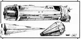
That's too tall compared to the S7 Keith drawing. I'm guessing, based on the hatch size between the two nozzles, that the height at the highest point is about 3 meters, and everything else gets smaller from there. A very lean ship.
S7 explicitly says 7.5 m high:
Skärmavbild 2023-08-11 kl. 09.37.png

S7, p3:
Skärmavbild 2023-08-11 kl. 09.40.png
That's about 9 m tall, which would make the hull about 95 Dt.
 
Last edited:
S7 explicitly says 7.5 m high:
View attachment 3802
But the base width (from which the angles of the diamond-shaped slices are determined) is not 24m.

Drawing it under the assumption that the top view angle is from being 24m wide, 37m from the nose (apex) will result in steeper angles for the sides, so it might appear taller.
 
Last edited:
The dimensions given in S7 can not be correct.
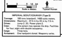
They would give a volume of ~1125 cubic metres or ~80 displacement tons.
 
Last edited:
According to the blurb and the deck plan the actual width is ~24 m. Yes, it would be wider if the edges weren't cut, but they are?
It is not 24m wide at the same place where it is 7.5m tall.

back measure.jpg
To get the correct pyramid-base shape (and area), you have to measure the area of the diamond-shape that the plane of the aft bulkhead would project if the corners were not cut away.

Then calculate how much the cuts remove, and deduct that when computing the volume.
 
Last edited:
The dimensions given in S7 can not be correct.
They would give a volume of ~2250 cubic metres or ~160 displacement tons.
Pyramid volume is (base area x height [i.e. length overall]) / 3.

Base area is 1/2 width x height (simplified from two triangles of area (width x (height/2) )
[EDIT TO ADD CLARIFICATION: base area is NOT width x height as with a pyramid with a rectangular base. This is a rhomboid base! You're welcome to do the math for calculating it as a rhomboid if you want, but be sure you know where the stated measurements go....]

Width is measured at the intersection of the extended side edges and the plane of the aft transverse bulkhead.

Calculate based on that, then subtract the clipped corners.


Red lines show the two triangles used to construct the base area, and the length.

Illustration does not clearly show the aft-corner clipping.

Untitled2.jpg
 
Last edited:
It is not 24m wide at the same place where it is 7.5m tall.
Image snipped out for clarity, but scroll up if it wasn't there when you first viewed the post. I've replaced it with a better one.
To get the correct pyramid-base shape (and area), you have to measure the area of the diamond-shape that the plane of the aft bulkhead would project if the corners were not cut away.

Then calculate how much the cuts remove, and deduct that when computing the volume.
Alternatively, you can determine the height at the section where it's 24m wide by multiplying the fraction of the overall length at which the 24m width occurs, by the 7.5m height. Then you have the correct proportions and can calculate the volume of the pyramid ahead of that section, but still need to calculate the volume aft of that....
 
Back
Top