• Welcome to the new COTI server. We've moved the Citizens to a new server. Please let us know in the COTI Website issue forum if you find any problems.
  • We, the systems administration staff, apologize for this unexpected outage of the boards. We have resolved the root cause of the problem and there should be no further disruptions.

Type ST Transport Scout: 199Td, J4/2G (LBB2 2nd Ed.)

Back to the ST.

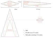
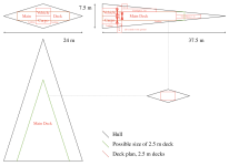
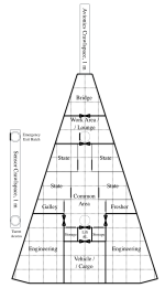
As I noted upthread, I based the hacked-up plans (see here) on the flawed canon Sulieman deck plans, scaled up. While I like the idea of it, doing a proper set of deck plans requires fixing the Sulieman plans first, then scaling the hull to "200"Td, then stuffing most of the Type S's interior layout into that hull, along with larger drives.
 
Fixing the Type S:
I'm seeing it as a pyramid with a diamond-shaped base, with the outer corners of the base shaved off.
Basic pyramid is 25.14m (before the aft corners get clipped to make it 24m wide) x 7.5m, by 37m tall (long).
Add maybe half a ton for the drives sticking out the back, then discount by about 1.1Td for the corner clips.

I get about 1138m3 after taking the corners out, but before adding the protruding drives. That's 84.33Td, call it almost 85 with the drives.

Someone want to check my math?
 
And of course I found the same problem everyone else who's tried to do a model of that ship -- or even tried to do a 3-view with the deck plans -- has run into over the last few decades. Stuff doesn't fit.

I mean, the cockpit kinda works. Floor slopes upward between the pilot and copilot seats, seats lean back a bit -- yeah there's space for it all. Bit cozy, but it works. Other than that, the whole main corridor is standard height all the way to the cockpit iris valve. The problems start outboard of the hallway.

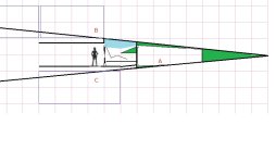
Then you get to this bit:
(A) is the floor hatch in the forward electronics crawl space.
(B) is the hatch to the attic (see 3m tall box showing where the deck should be)
(C) is the hatch to the Forward Cargo Bay (see the other 3m tall box, as above).

What.
FrontS.jpg
And this is the tallest part of the side view (centerline ridge).
Haven't even gotten to writing about the forward staterooms, but the outer edges geometrically can't be over 0.8m (2.5') tall at the front corners -- and that's going to mess up the floor height.
 
Last edited:
I sort of get what they were trying to accomplish -- the upper and lower "decks" aren't meant to be full decks, just crawl-spaces. But it's not even arguably tall enough to permit even a crawl-space until another 4.5m aft of where the hatches are placed. It's tight going even at that point, but you can at least make the argument with a straight face.
 
The moral of the story is that the deck plans as drawn were more "aspirational" than something cross checked with a 3D model of the volume (which would have required architectural training and drafting skills back in the late 70s/early 80s).

To put it politely, the deck plans seen in LBB S7 were drawn up using what amounts to pre-CAD design tools.
We've got better desktop publishing tools now, not to mention superior compute power for drawing this stuff on (actual) computers for iterative design work.

The other problem your analysis of the 3D space is also going to run into regarding the sloping sides of the pyramid. So if you yaw your concept drawing 90º to look at the taper towards the edges towards port and starboard and you have to start wondering if there's enough height to fit decks into alongside the centerline. The sheer number of "slices" through the hull you would need to generate to cross check the 3D volume availability at every point along the hull would be potentially prohibitive (short of using actual 3D software to do the work).
 
The moral of the story is that the deck plans as drawn were more "aspirational" than something cross checked with a 3D model of the volume (which would have required architectural training and drafting skills back in the late 70s/early 80s).
Algebra, geometry, a calculator, and middle-school mechanical drawing. :)

Yeah, I used a spreadsheet and MS Paint because I'm lazy, but I could have done it in the early 80s by hand if I realized it needed to be checked. (At the time, the only published deck plans I had were from Snapshot, AHL, and -- I think -- Broadsword.).
 
All you need is a bit of basic geometry?
Huh.
Well whaddya know?
All you do need is a bit of basic geometry (and the tools necessary to draw it out properly).

That 3m deck line though ... ouch.
Looks like it's time to do some radical reorganization of the classic LBB S7 Scout/Courier deck plan in order to make things fit inside it better.
In theory, you allocate the odd shaped three dimensional rhomboids as fuel tanks.
Oh definitely!
All the "leftover" displacement outside the pressure hull would DEFINITELY be used for L-H2 tankage. (y)
 
Yes. Basic geometry.

(Give me a few minutes and I'll post sketches.)
(No sketches. And @AnotherDilbert did them anyhow. :) )

We know the shape is a pyramid (with clipped aft corners).
Project the edges of the hull plan out to the plane of the aft bulkhead.
Extend the line of that bulkhead across to meet those projected lines.
Measure the width at the intersection.
That and the stated height give you the dimensions of the pyramid's diamond-shaped base.
Critically, it provides the ratio of height (given as 7.5m) to width (25.14m before corner-clipping) of the base.
Every section taken parallel to the longitudinal axis will be a diamond of these proportions (except where clipped -- those are irregular hexagons).
Measure the width at relevant points, and you know how tall the corresponding diamond section will be.

Draw the important diamond sections (front of cockpit, middle of cockpit, beginning of stateroom block).
Overlay horizontal lines on them at 3m (total deck height) and 2.13m (floor-ceiling height) separation, centered on the hull maximum width.

To find the longitudinal location where the stateroom block's 3m x 7.5m cross-section fits entirely within the hull, draw half a diamond that's large enough, and where a horizontal 1.5m (above the centerline) line meets the angled hull, measure 3.75m toward the center, then measure the height of the diamond that would be centered on that vertical line. Use that to calculate the width of the diamond at that point. Then, find the location on the deck plan where the hull is that width -- there's the place where it's inside the hull from there aft.
 
Last edited:
I think the forward pair of staterooms can be saved, but they're going to be kind of claustrophobia-inducing.

The lower cargo bay can't exist (maybe a ventral hatch can, though) and the upper crawl-space has to start further back
 
Well, my favorite Scout config is simply the one in the drawing in S7, the thin, "can't even stand up in it" version. Always been in my eye the way it should be, and seeing "authentic" renderings, as well and the 3D printed models, yea, no thanks. Fat sow in contrast to the sleek, star jumpin', planet explorin', called up in times of danger Scout.
 
Well, my favorite Scout config is simply the one in the drawing in S7, the thin, "can't even stand up in it" version. Always been in my eye the way it should be, and seeing "authentic" renderings, as well and the 3D printed models, yea, no thanks. Fat sow in contrast to the sleek, star jumpin', planet explorin', called up in times of danger Scout.
I like the shape, and I think it can be saved, mostly. (As noted, no lower cargo hold and the attic crawlspace starts further aft.) It's on the small side of the drafting-error allowance (about 85Td) so it should be ok.
 
The cockpit works as a cockpit rather than a flight deck. Crew are seated Sports-car Supine rather than Van Vertical -- it's a side-by-side fighter-jet cockpit, not an ocean-going ship's bridge.

The first set of staterooms, though? Oof.
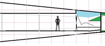
Let's draw them up. This is the section from the cockpit to the second pair of staterooms, with the hallway wall and room doors removed.
The grey diagonal lines outline the far wall of the staterooms (where the wall hits the hull -- it's probably shorter than indicated).
For reference, the figure is 183cm (6') tall.

It sorta works.
Bridge to SR3&4.jpg
Going to have to duck anywhere inside there.
Bed probably goes outboard and forward, and you're only really going to be sitting up in bed near the aft end of it (head of the bed).

You aren't going to be using them for double-occupancy except by sleeping in shifts.

The aft staterooms aren't terrible, but still have low ceilings.

Everything aft of it (common area, drive bay) has at least 3m vertical clearance.

Sliding the aft wall back 1.5m (so the fore staterooms are 6m X 3m and the aft ones are 3m X 3m) might balance things out.
 
Eagle transporter - the seats slide (couldn't find an illustration).

If I recall correctly, you have a twenty tonne bridge, so plenty of space.

If it was the MongoVerse, six tonne small bridge, cramping causes minus one to bridge activities.
 
If I remember correctly, the Judges Guild's Type S was a single deck design. I'll have to dig around and try to find my copy. GDW's first Type S the one in Snapshot was also a single deck design. So, CT Supplement-7 was the first to try to make it into a multi-hull ship. I wonder how close the early designs were.
 
Back
Top