• Welcome to the new COTI server. We've moved the Citizens to a new server. Please let us know in the COTI Website issue forum if you find any problems.

CT Only: Fixing the Type T Deck Plans?

The Type Y "payload" is 40Td as 10 staterooms (7 for guests, 2 for the owner, 1 for a steward), plus vehicles and cargo.
That'll be interesting to fit into the cargo hold...


I'll dispense with the ATV and Air/Raft, and swap in a "Limo" that's either a re-skinned GCarrier or a Speeder with a quarter of an Air/raft grafted into the middle (I'll work that bit out later -- either way, it fits in the GCarrier bay).
Just up the TL a bit and make it faster. The air/raft and GCarrier are just very basic, low-tech examples.

Or you can build something reasonable with MT. TL-13 can give you a very capable vehicle at 8 Dt.
 
That'll be interesting to fit into the cargo hold...
It's possible, but it's going to look rather ad hoc for metagame purposes (the PbP). The extra accommodations might just be an easily-removed block of modular cabins on one or the other cargo decks. The idea is to give the PCs a Type T with at least one luxury passenger stateroom (converted from the barracks) as a nod to the status of the "owner" (it's technically on loan from the IISS). The rest is gravy.
Just up the TL a bit and make it faster. The air/raft and GCarrier are just very basic, low-tech examples.

Or you can build something reasonable with MT. TL-13 can give you a very capable vehicle at 8 Dt.
True. I'm in a hand-waving frame of mind about this. The cost is mostly irrelevant to the scenario, and the capabilities will mostly be driven by the plot (lightly armored and with some defensive systems because it's for a planetary-level VIP).
 
Last edited:
I put up a really crude rendition of the VIP transport conversion over on the Boughene Station Blues OOC thread.
Adds 6 modular staterooms in the cargo hold. There's a potential to add another two, to complete the Yacht specification (except for the ATV, but why bother with that when you have good grav vehicles?).

Even that wouldn't be a Yacht, per se. Actually turning it into something truly "yacht-like" would require moving bulkheads and such, because the added passenger space in the cargo hold is not laid out particularly well. I'd move the GCarrier (or its replacement) down into the hold, and put a couple of staterooms in the attic -- with lots of windows. A personnel lift would replace the freight elevator to free up some deck space, and some of the inter-deck iris valves would be relocated. I'm not really planning to do that one up at the moment, though.
 
Reaching back a bit:
I was motivated by the realization that the cover illustration came from a different set of deck plans than what got published. At first, I thought it was just minor changes... Once I realized that the original plans got lost along the way, I felt compelled to bring them back as best I could.
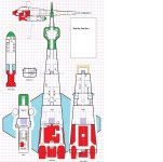
Which gives me another project. This is my "modern interpretation" of deck plans corresponding to the original illustration, but I'm pretty sure the original deck plans that either led to or were informed by that illustration didn't look like that. The key differences are that I'm using 2Td cabins with 2Td shared space, where the original almost certainly used 3Td cabins with 1Td shared space -- and I gave all the flight crew individual cabins (same total volume of staterooms, just divided up differently), where the original had the gunners in literal double occupancy.

And it gets around to something I'd seen mentioned fairly recently. IIRC, the Type T wasn't in 1st Edition. It seems to have made it into 2nd Edition because it was cool -- that is, someone designed it, drew up the plans, and used it in someone's game. I say this because the choice of putting the gunners in double-occupancy staterooms is oddly specific. Ship's troops, sure. But if you're putting some of the flight crew into double occupancy, why not all of them (except the Captain and maybe another officer or two)? The rules say you can do it, so why didn't they? It's not like there isn't enough room by the numbers; after all, the ship has about 50Td of cargo hold and it can't all be missile magazine space!

I think they had a specific set of deck plans in mind when they added the writeup to LBB2 '81, one in which two more 6-deck-square staterooms wouldn't fit without looking extremely awkward.

The "other project," then, is to try to reconstruct those original plans. I'll get to it eventually.
 
Last edited:
It also occurs to me that the FASA plans were "legal" -- though incorrect by the LBB2 '81 writeup -- if the Captain and another officer (Chief Engineer, Navigator, Medic, or Lead Gunner) were the only ones in single-occupancy staterooms.
 
How about an emergency hatch between the crew deck and troop deck?

It would simplify evacuations either to the boat or up through the attic crawlspace, especially if power is out?

... It's not a bad idea; I'm just not sure it's necessary. In addition to the elevator and bypass hatches up front, there are the freight elevator and inter-deck iris valves at the aft end of the cargo hold.
Also, most evacuation scenarios would be from battle stations, not from quarters. The only personnel on the upper quarters deck in that situation are the laser gunners, and they're right next to the elevator and elevator emergency bypass hatches. The missile gunners and engineers evacuate through the upper cargo hold to the Ship's Boat's cargo hatch in the floor of the lower cargo hold.
 
It also occurs to me that the FASA plans were "legal" -- though incorrect by the LBB2 '81 writeup -- if the Captain and another officer (Chief Engineer, Navigator, Medic, or Lead Gunner) were the only ones in single-occupancy staterooms.
It's quite legal all around.

"Stateroom" need not map directly to a cabin on the deck plan. "12 Staterooms" just means (about) 48 Dt accommodations in as many cabins and rooms as you like. You could toss all the troops and gunners into a single large barracks room, if you wanted.

Look at the Kinunir deck plan with a mix of different-sized cabins and barracks. The Captain has a nice suite IIRC...
 
Deck plans formatted a bit.
1 grid square: 1/4"=1.5m.
The source image can be printed at that scale on 8.5x14" legal-size paper. Not sure why you'd want to, but you could.

The map legend is a bit out of scale -- borrowed from a previous project and lightly edited. Still a work in progress.

I'll re-do the plans in sections at 1/2"=1.5m at native resolution rather than the double-sizing I posted upthread.

Comments, suggestions, and/or concerns?
Demo Top Fuel.jpg
 
Last edited:
LO = Low Berths?
The nearby airlocks are downwards, no hatch in the wall (to the fuel tanks), but downwards. Excellent place for maintenance access to the wing tanks?

Now that you mention it, I see ventral and dorsal access, but no side access? Well, I guess the wing would block direct side-by-side ship-to-ship docking anyway? Except for long ungainly foldable plastic tubes...
 
It really help me to see the ship at a glance if all the decks are side-by-side at the same level. It's much easier to see which hatch connect to which hatch on the other deck. That is perfect here, except for the ship's boat...

I would find it easier to read if the ship's boat was beside the lower deck. Or at the very least an overview showing how the decks fit together?

Something like this (but the entire ship), but smaller, perhaps?
Aft Side Demo.jpg
 
LO = Low Berths?
The nearby airlocks are downwards, no hatch in the wall (to the fuel tanks), but downwards. Excellent place for maintenance access to the wing tanks?

Now that you mention it, I see ventral and dorsal access, but no side access? Well, I guess the wing would block direct side-by-side ship-to-ship docking anyway? Except for long ungainly foldable plastic tubes...
LO is indeed Low Berths. (Not much room for text at 1/4"=1.5m scale...)

In the original, the "hatches to the fuel tanks" were almost certainly for underwing or overwing exits. Might have been mentioned in the accompanying documentation, but it's not clear on the plans. They might even have been to the balconies formed by the weird notches at the wing leading edge roots?
Capture.JPG

I'm positing that the port ventral airlock has retractable stairs and the starboard one has a retractable docking tube. The starboard-side landing gear includes magnetic grapples to provide a stand-off docking capability when the Ship's Boat is attached. Fold the lower tip fins, extend the starboard-side gear (past the ship's boat), lock those onto the guest ship's hull, and extend the docking tube.

No lateral access, because of the wings.
 
I would find it easier to read if the ship's boat was beside the lower deck. Or at the very least an overview showing how the decks fit together?

Something like this (but the entire ship), but smaller, perhaps?
Can do. Thought I'd already posted it, but it might be a few pages back by now. Needs minor corrections (this version pre-dates expanding the crew quarters, so it doesn't show the Troop Ready Room as the airlock to the Ship's Boat).
Edit: Replaced attachment with updated version.
Edit 2: Corrected "Ready Room" floor hatch to an iris valve.


Note the size of the tip fins (measured from the illustration). The lower sections have to hinge at about 4.5m below the wing in order for the fin tips to clear the ship's boat when retracted...
Side View2.jpg
 
Last edited:
Or a one-click option to flood the airlocks with -250oC liquid hydrogen...
Squeamish, are we?

Really, you have two airlocks, so a minimal risk of temporarily disabling one airlock is acceptable?
Where would be a better place for a maintenance hatch into the tanks?
Make the hatches pressure sealed, opening into the tanks, so they can't be opened while the tanks are pressurised?
 
Exactly!

Please include it in the deck plan poster?
That's the plan.

It'll be a separate sheet though.

The final version will be the top view and side view, each in 1/4"=1.5m (pretty much as-is), plus section-by-section plans in 1/2"=1.5m (such as I've already posted, but re-drawn at higher resolution to eliminate the "hull by Lego*" effect).

I'm pretty sure it'll be formatted for 8.5"x14" Legal sheets, because that's necessary for the top and side views and the rest should follow for consistency.

For extreme silliness, I might do the top view in 1/2"=1.5m on four sheets of 8.5x14", though actually aligning the edges when dealing with the resulting printouts would be extremely annoying since I don't expect to be able to print all the way to the edges of the sheets.

And detailed written descriptions, while I'm at it.


--------------------------
*TL-6 area-denial weapon -- like caltrops, only worse. Sometimes the old ways are the best...
 
Last edited:
Squeamish, are we?

Really, you have two airlocks, so a minimal risk of temporarily disabling one airlock is acceptable?
Where would be a better place for a maintenance hatch into the tanks?
Make the hatches pressure sealed, opening into the tanks, so they can't be opened while the tanks are pressurised?
Extra-credit points:
- Response to flooding the airlocks with LH2 is to either break off the docking attempt to disperse the fluid, or blow through the inner airlock door for the same effect. Unless the next compartment has the O2 fraction cranked way up, in which case the ensuing deflagration blows the docked vessel away from the ship, likely punching the boarders' airlock doors out for good measure.

Yeah, there ought to be a tank maintenance access, and it needs to be pressure-sealed. Not sure it needs to be called out on the plans though -- the "hatches into the fuel tanks" are just an artifact of the FASA plans being unclear. I don't have a copy, so I don't know if the accompanying booklet explains what's going on there. I seriously considered adding ceiling iris valves there as well, so as to provide over-wing exits in addition to the under-wing ones. Not really necessary, though, since the "loading bay" hatch gets you onto the upper surfaces of the hull if needed.
 
Exactly!

Please include it in the deck plan poster?
That took me down a rabbit-hole: formatting issues.

I originally thought I'd do it as a series of 8.5"x11" sheets (as with the demo versions upthread) to be mentally stitched together (leave one sheet, move to the next sheet down the line), with the side view as a few corresponding 8.5"x11" sheets. It can be done as four 8.5"x14 (legal size) sheets as a single "poster", but that poses the problem that many computer printers can't print to the edge of the sheet, so (for example) the main corridor down the ship's centerline on the main deck would just have the outer edges of the assorted hatches and a (likely) 1/4" wide strip of white space down the middle.

I'm wondering which layout would be most useful. The advantage of using standard paper is that, well, everyone has it on hand. The advantage of legal-size paper is that everything fits. Doing it as a single poster at "full scale" (1/2"=1.5m) is going to make for a rather large file...
 
Back
Top