• Welcome to the new COTI server. We've moved the Citizens to a new server. Please let us know in the COTI Website issue forum if you find any problems.

CT Only: Fixing the Type T Deck Plans?

When I look closer, the taper looks flatter than an ellipsoidal cross-section, more like a squashed hexagonal shape perhaps? That would make it easier to accommodate the decks within the hull shape.
I agree. (y)
Perhaps more of flattened octagon than a flattened hexagon, but this is a very good insight for any 3D modelling that wants to hew more closely to the FASA art image provided.
the original FASA version was only a little chunkier in the ass (from the original post):
Type T.JPG

The bridge bulges still look mighty wacky. :cautious:
 
Look at the DA1 Annic Nova deck plans. The only way to load cargo is directly from one of the two pinnaces. There is no other cargo door. I mean, well, yeah, you could toss break-bulk cargo from a shuttle's cargo hatch into the docking receptacle, then shove it sideways into the cargo bay... but you really don't want to be doing that.
Yes, but it has a perfect excuse: It is alien and mysterious.

But seriously it's unstreamlined, it's supposed to be loaded and unloaded by small craft.
 
Yes, but it has a perfect excuse: It is alien and mysterious.

But seriously it's unstreamlined, it's supposed to be loaded and unloaded by small craft.
But that precludes it being loaded by anything bigger than a pinnace. Say, a Shuttle...

It has a 150Td cargo hold. As written (1st Ed), pinnaces have about 12Td cargo capacity, probably a bit more if they're not carrying extra fuel.
That's a lot of runs out to the jump limit...
 
But that precludes it being loaded by anything bigger than a pinnace. Say, a Shuttle...
That docking port might be a standard docking port in its home civilisation. There is no reason to assume it is built to Imperial standards.

The builders might ask why the Imperium builds such useless small craft?
 
Yeah, but it's bit weird (ok, aliens gonna alien) as a docking port that'd work with a 95Td shuttle, let alone anything bigger.
 
I see what you mean.

Yes, but the original FASA version was only a little chunkier in the ass (from the original post):
View attachment 2619

Later version gained a bit of weight aft, presumably to accommodate the deck plans.

But, agreed, we could extend the top and bottom decks a bit outside the basic hull taper, but not very much I think.

When I look closer, the taper looks flatter than an ellipsoidal cross-section, more like a squashed hexagonal shape perhaps? That would make it easier to accommodate the decks within the hull shape.
What's going on with that bulge/curved bit on the underside, at the wing/fuselage junction? There's something there that occludes part of the distant-side tip fin... the nose of a standard Ship's Boat, perhaps?
 
I agree. (y)
Perhaps more of flattened octagon than a flattened hexagon, but this is a very good insight for any 3D modelling that wants to hew more closely to the FASA art image provided.


The bridge bulges still look mighty wacky. :cautious:
They're trying to be fighter-jet "bubble cockpits" (in-universe justification). Or they're the eyes of the mosquito that inspired the drawing...
 
What's going on with that bulge/curved bit on the underside, at the wing/fuselage junction? There's something there that occludes part of the distant-side tip fin... the nose of a standard Ship's Boat, perhaps?
The deck plans says no. The boat is non-standard and in an internal hangar.

From the original post:
Type T Decks.JPG
 
Yes, if the black marking between the bulges are the windows to the bridge, the bulges might be sensor domes?
Actually, since I've been roughing out my own deck plans, I think I have a better idea, springboarding off @magmagmag's work of making the bridge bulges into big "bubble eye" dome windows.

Put holo work stations there.

You would need a large volume of space for a holographic projector and work station (as ship equipment, rather than something portable you could put on a robot, for example) and those extra spaces are exactly what is needed to give you that extra volume to work with. That way, you have have 4 holo work stations in each "bug eye" (1 oriented forward, 1 oriented aft) where crew have a decent "bubble canopy" view outside the ship for direct visuals (useful for docking maneuvers) and also have 3D holographic displays for information (useful for 3D space). Controls could still be touch screen stuff (ST: TNG) or brightly lit "chicklet" color coded buttons (ST: TOS) rather than full on holographic controls too (upgrade option at TL=13+).

TTB shows that holographic displays are available starting at TL=10.
What's going on with that bulge/curved bit on the underside, at the wing/fuselage junction? There's something there that occludes part of the distant-side tip fin... the nose of a standard Ship's Boat, perhaps?
You appear to be correct!
I zoomed in the image by 400% and snipped out the ship in the upper left which is presenting the ventral side as seen from below.

8sC3FcK.png


It's dark and difficult to see, but that outline STRONGLY SUGGESTS a LBB S7 standard 30 ton Ship's Boat "tube" slung under the ventral fuselage. Basically, there's a hollowed out form factor in the hull which the Ship's Boat would nestle up into for docking clamps to grab onto, so not an enclosed berthing placement, but one where you only need an airlock to access ship to boat.

Docking is probably done at a 90º roll position so as to orient the port side airlock "up" into the ship for a hard airlock docking seal.

Good catch! (y)
 
More like the rules don't properly address it.
It's not that the rules DISallow it with an explicit prohibition (or even a head fake in that direction) ... it's more a case of the rules not addressing the concept (properly) in the first place.
LBB2 did not address this at all, hence the Subbie.
LBB5'79 didn't either, hence the Gazelle.
LBB5'80 does address this, however clumsily:
Small craft are either internal, or external (Dispersed Structure configuration).
The advantages of Dispersed are obvious: craft are carried at no extra tonnage (just the crafts own tonnage), and all craft can be launched simultaneously. The disadvantages are that the ship is unstreamlined (hence can't refuel itself), whether carrying craft or not, and they can't be armoured.
HG'80, p32:
Small Craft: Various non-starships (such as pinnaces, cutters, ship's boats, shuttles, lifeboats, and fighters) are detailed in the section on small craft. Small craft are carried at their own tonnage on ships 1000 tons and under; they require tonnage equal to 130% of their mass within the hull of larger ships. The cost is Cr2,000 per ton.

...
Vehicle Launch Facilities: Starships and non-starships carried on a ship must be provided with some form of launch facilities.
1. Dispersed Structures: Ships which have a type 7 configuration hull carry craft and ships attached to their exterior. They need no additional fittings. All craft carried by a configuration 7 ship may be launched in one turn.
2. Launch Facility: Ordinary launch facilities for a ship allow one craft to be launched per turn per 10,000 tons of hull. These facilities are available at no cost or additional tonnage.
The tonnage of the craft is included in the hull of the ship, whether dispersed or not. The ship does not have reduced tonnage when the craft are launched, and drive performance is not recalculated.

To launch more than one craft per round, the ship must generally either be Dispersed config, or have large Launch Tubes.


The closest you get to it is L-Hyd drop tanks, which are explicitly external and thus drive performance gets reduced.
Well, if you can stick a drop tank on a ship ... is there anything else you dock with and transport externally?
Yes, drop tanks are the novelty, with the new mechanism of recalculating drive performance specific to drop tanks. TCS clarified and extended that to Exterior Demountable Tanks.

TCS did clarify fittings for carried craft, but did not extend drive recalculation to them.

If you account for the tonnage of small craft as part of the basic design (counting it as "internal" allocation, even if it actually isn't) the ship's drives are going to be rated for the combination (370+30=400 in this example). Drive performance doesn't go up when the small craft leaves, but it doesn't go down either when the small craft is docked.
Agreed. Note that the Hull in this case is 400 Dt and does not change.

Whether a docking point is an internal hangar with doors and pressurization or merely just a conformal negative space to nestle up against the hull doesn't make any meaningful difference to LBB5.80. Those kinds of differences are essentially "fluff text" on the design, because the math for it doesn't change.
We can perhaps stretch the rules for the Subbie or the Gazelle, as there is some wiggle room for small ships, but the Mercenary Cruiser is specifically not allowed under LBB5'80: Small ships can only launch one craft per 20 min round without launch tubes or extra bays (unless Dispersed, of course).

Carrying two craft externally that can be launched simultaneously would make it a Dispersed ship and hence unstreamlined.
 
So I've continued advancing my Patrol Corvette deck plan forward of the engine room.

I've got the single occupancy staterooms for the 4 ratings who are the junior crew members.

There's also a medical bay with an autodoc bed and a medical bed inside of an internal bulkhead space with tint for privacy "bulkhead windows" along the sides as the duty station for the ship's one medic (who needs skill-2 for better survival rates on low berth resuscitate rolls).

There's a very small crew lounge space (3x2 squares) that uses privacy curtains to help control light levels for the recreational holoviewer, along with a kitchen counter with two sinks on the ends in case anyone wants to do some more "hands on" meal prep. The holoviewer in this lounge space will also typically be used (with curtains pulled aside) for any All Hands Briefings for the crew and security detail.

Individual 1x1 squares for life support equipment have been added, along with lockers to help square up the internal spacing thus far. The aft lockers near engineering are for engineering tools and equipment. The forward lockers a step away from the medical bay are for vacc suits.

Further forward of the vacc suit lockers will be dual airlocks (iris and hatch) side by side on both the port and starboard sides, complete with an extensible airlock that can be used for transfers and boarding actions while abeam of other vessels. The life support spaces forward by the vacc suit lockers are primarily for cycling the airlocks. The life support spaces aft near engineering are linked into the fuel purification plant in order to "top up" onboard O2 and H2O along with other desirable chemical products using the "waste chemistry" stream from fuel purification yielding refined liquid H2 of high purity. Useful chemical elements that are essentially "fuel waste" can be "refined out" and retained to mitigate the inevitable losses within the ship's life support systems and help maintain adequate reserves.

The fuel scoops at the wing roots have been added, along with retractable telescoping robotic arm fuel probes on sliding tracks useful for fuel transfers between ships. The fuel purification plant spaces have also been added, with the (former) iris valve at the grav lift being replaced by yet another pressure door for a pass through access to the fuel purification plant. A maintenance hatch for access into the fuel tanks in the wings has also been added. Monitoring of fuel purity and refinement quality is handled by the engineering workstations immediately inboard forward of the drive room.


Forward of this rectangular block of hull spaces is where the hull begins to narrow through the lateral redundant airlocks, the officer stateroom quarters, the model/4fib computer, bridge and avionics spaces.

Might need to see if I can squeeze in a couple of small weapons lockers in some of the "not exactly square" waste space forward of the bridge.


Still rather pleased with my efforts on this latest draft so far.
There's be a LOT of trial and error just to get to even this partially completed point, of course ... but it's been quite fun thinking about what it would be like to actually LIVE aboard a ship like this. 😁
 

Attachments

  • Patrol Corvette Engineering Deck 1.png
    Patrol Corvette Engineering Deck 1.png
    297.3 KB · Views: 18
It's dark and difficult to see, but that outline STRONGLY SUGGESTS a LBB S7 standard 30 ton Ship's Boat "tube" slung under the ventral fuselage. Basically, there's a hollowed out form factor in the hull which the Ship's Boat would nestle up into for docking clamps to grab onto, so not an enclosed berthing placement, but one where you only need an airlock to access ship to boat.

Docking is probably done at a 90º roll position so as to orient the port side airlock "up" into the ship for a hard airlock docking seal.
I'd get silly and allow the boat to rotate on its longitudinal axis in the docking grapples; or in a less silly variance, add hatches to its roof.
 
The deck plan also says the boat is 26Td.
And the boat bay is over 40 Dt, presuming uniform standard deck height. Good enough?
Or perhaps deck height isn't uniform?

LBB2'81, p21:
Finally, a leeway of plus or minus 10% to 20% should be allowed. If the final deck plans come within 20% of the tonnage of the ship specifications, then they should be considered acceptable.
 
So I've continued advancing my Patrol Corvette deck plan forward of the engine room.
The geomorphs looks much better than empty rooms.

Individual 1x1 squares for life support equipment have been added, along with lockers to help square up the internal spacing thus far.
I don't think you need specific squared for life support etc. as we have quite a lot of space between decks for that. But the access panels should make maintenance easier.

The aft lockers near engineering are for engineering tools and equipment. The forward lockers a step away from the medical bay are for vacc suits.
More lockers are good, I had too few in my design.

If you mirror-flipped the rear staterooms, you could get the doors into the corridors besides the med bay, letting the crew commons be a little less disturbed? It might make it easier to let the crew commons spill into the "corridors" between the staterooms and the curtains and feel a little roomier?

I might make some more room between the drives for maintenance access?

There's be a LOT of trial and error just to get to even this partially completed point, of course ... but it's been quite fun thinking about what it would be like to actually LIVE aboard a ship like this. 😁
In my limited experience good deck plans takes a lot of time... Iterating over the design a few times generally lets out a few more ideas.
 
The geomorphs looks much better than empty rooms.
Aye. (y)
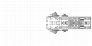
It's also more than 10x the work of empty rooms, but it does convey a much more immersive sense of the internal spaces. The geomorph snippets make it possible to envision life aboard in an immersive way, rather than in an abstract imaginary way.
I don't think you need specific squared for life support etc. as we have quite a lot of space between decks for that. But the access panels should make maintenance easier.
"NEED" ... no.
But I had "leftover" 1x1 squares to fill in order to keep the corridors running smoothly, so I just filled in the available spaces with life support equipment.

If you need lockers for vacc suit storage, you also ought to have a place for airlock atmosphere compression/decompression storage so you aren't venting all that usable air out into space somewhere. Makes it "feel more real/reasonable" to do that.
If you mirror-flipped the rear staterooms, you could get the doors into the corridors besides the med bay, letting the crew commons be a little less disturbed?
Actually, after I posted the last image, I decided that I wanted to add a desk and chair into the 4 staterooms, but in order to do that I needed to move the entry doors from one end of the stateroom to the middle. Took a bit of editing work, but I'm even more satisfied with the result. Also added sliding doors to the Fresher area of each stateroom where the dedicated full shower with independent sink and toilet are located (rather than relying on the more typical "all 3 in 1" arrangement.

Problem is, I won't be able to use that arrangement in the officer quarters, since those are oriented the other way to the corridor (short end access instead of long end access) so I'm going to have to work out an alternative there. :unsure:
It might make it easier to let the crew commons spill into the "corridors" between the staterooms and the curtains and feel a little roomier?
The point of using the privacy curtains is that they can be easily slid aside (just like curtains) so they're a temporary partition (of convenience rather than a permanent one. The privacy curtain can be opened for wider access to the corridors (and allow more standing room only attendance at holo briefings).
I might make some more room between the drives for maintenance access?
The proportional shape of the deckplan is already veering far enough away from the hand drawn art depiction. I don't want to deviate even more (than I have to) in order to detail Jeffries Tubes and crawlspace access, which would clutter up the image even more than it already is.

Plus, if the space is enlarged, how is that going to be reconciled with the 35+15+25=75 combined tonnage of drives called for by LBB2.81 standard drives? 75 tons means 150 deck squares (give or take a few). I've got a 19x8=152 square drive room. The only way to get even closer to 150 squares would be a 15x10 drive room, but that would be even wider from port to starboard than what I've already got and make the ship "even chunkier" in lateral cross section.

Easiest way to add more crawlspace between the drives would be to take out the "wings" of batteries (the hexagonal pieces) wrapping around the "boxes" in the jump drive. Doing that makes the jump drive look less impressive, but is certainly doable. It would require an "ugly ugly hack" in order to edit those "wings" of batteries out ... or simply starting over (which under the circumstances might be preferable, all things considered) in order to implement that change.

Let me think about it.
The reason I put those "wings" in on the batteries was mainly to account for the 6 tons of jump capacitors that a 400 ton jump-3 starship ought to have (as specified by the LBB5.80 Black Globe rule, which I see no reason to ignore). Without the "wings" of extra capacitors they looked a bit shy of 6 tons (12 deck squares) worth of area (more like 5 tons, 10 deck squares) ... but if better work access is "needed" then those "wings" of capacitors in the jump drive would be the best thing to trim, creating the necessary walk/crawlspace between the jump drive inboard and the power plant/maneuver drives to port and starboard. The transverse EPS transfer unit in the center would be more of a flattened ovoid shape (to fit the drive room into the 3m height of a single deck) and could have some over/under space to get past it to the aft end of the drive bay.

Hmmm ... rather convincing point.
Only thing giving me pause over implementing the notion is the amount of work that would be involved to either edit or start over (again).
Although, to be fair, I've been getting a lot more proficient at manipulating the geomorph snippets, and would have the existing work to reference for the exact placement of everything.
 
Plus, if the space is enlarged, how is that going to be reconciled with the 35+15+25=75 combined tonnage of drives called for by LBB2.81 standard drives? 75 tons means 150 deck squares (give or take a few). I've got a 19x8=152 square drive room. The only way to get even closer to 150 squares would be a 15x10 drive room, but that would be even wider from port to starboard than what I've already got and make the ship "even chunkier" in lateral cross section.
If you are within 10% you are golden. Deck plans are rarely perfect.

I think we can say that that 75 Dt is for the engineering compartment, not necessarily only the drives. For it to work, there has to be maintenance access, so access space is included in the 75 Dt. We can even throw in some control stations, and perhaps even some basic workshop space, for good measure.

I like to think of it as e.g. the power plant is not just a reactor, but all the systems needed to produce power safely for years, more like an entire power plant building than just a boiler.

Many deck plans are fairly open and airy in the engineering compartment, e.g. this detail from the Kinunir:
Skärmavbild 2022-04-10 kl. 15.08.png
Note that the ship has no specified "machine shop", they just took a part of the drive space and called it a workshop, and that is perfectly fine.

Just as "staterooms" are not only sleeping cabins, but all living spaces that makes the ship liveable, if you see what I mean.
 
The reason I put those "wings" in on the batteries was mainly to account for the 6 tons of jump capacitors that a 400 ton jump-3 starship ought to have (as specified by the LBB5.80 Black Globe rule, which I see no reason to ignore).
The default capacitors are included in the basic jump drive. They are used as a buffer to channel energy from the power source to the jump process, I believe. No need to allocate extras.
 
Back
Top