One interesting bit is that it really doesn't look like there'd be room for a ship's boat in the spot that the FASA plans say it's supposed to be, due to the way the top deck slopes aft and its sides slope inward. And the top deck isn't full-width in any case, despite what the plans show.
That's what happens when you're drawing without 3D modelling being available to you. You just sort of "guess" and go with whatever "looks good" for the 2D art.
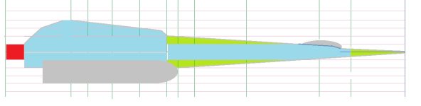
Also, doing the sectional slice at the flight deck bubbles shows that there's easily room for three-across seating. Pilot, navigator, Chief Engineer (or, if we're doing High Guard -- sorta -- manning, swap the Gunnery Officer for the Chief Engineer). That explains the weird front windshield between the bubbles.
If you do a 3 across arrangement like that, where are you going to put the access hallway/crawlspace/Jeffries Tube up into the nose cone to have access to the computer/avionics equipment forward of the bridge?
Also, from a practical standpoint, even if you put a workstation
right up against those windows on the centerline ... what would you be able to see out of them?

Short answer ... almost nothing useful for where the ship is going.
Why?
Because the sight line out of them would be basically worse than a Concorde with the nose in the "up" position.
You would basically need to have another set of windows in the "floor" in order to see "down" through them towards any landings you might want to be doing.
Here, let me take your Side Slice 2 image and do a bit of markup on what you would be able to see out of those black markings between the bridge bubbles.
That is some MIGHTY POOR VISIBILITY for anything having to do with anything akin to a visual landing (let alone a precision landing).
Even with a Concorde style "nose drop" your lateral visibility range is going to be mightily impaired for any kind of VTOL, especially if the ship is oriented more or less "deck planes level" for a landing because of where the windows are
between the bubbles.
I know the ship will have gravitic maneuvering control, so you could potentially do a "lawn dart" maneuver of aft up/nose down towards the ground to see where you're going for a visual landing (so more of a nose sitter than a tail sitter) before holding the nose steady while pitching the aft end down 90º before descending the last 10-20 meters or so to settle into a VTOL spot in a gravity well ... but I can't imagine wanting to attempt such a maneuver more than once!

After all, if you mess it up ...

... NONE of the failure modes are going to be pretty (or graceful) ...
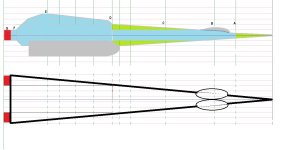
This is why I prefer the idea that the bridge bubbles (port/starboard) are where the actual bridge workstations are located, and that the upper surface of the bubbles has a retractable hull shield to reveal with windows on the upper surface for visual control situations. You also wind up with a visibility range more like this with the dome shields retracted:
It's basically the difference between a bubble canopy for a fighter jet and a concorde cockpit with blinkers on the side windows.
The bubble canopy has LOTS of visibility.
The cockpit with barely 2 windows has almost NO visibility aside from a "soda straw" almost directly forward (where if you can see something and it isn't moving in your field of view on approach, that means you're on a collision course).

I figure the two black triangles we see on the art between the bridge bubbles are just "standard fixed windows" carried over from ships like the Type-S Scout/Courier which are intended for use as emergency backup (in case ALL ELSE FAILS!) rather than as the primary windows to be used during all visual approaches as a matter of standard operating procedure with the work stations directly behind/under them along the ship's centerline.
The bridge bubbles, on the other hand, are large enough to host a large 3D holographic display (or two) and a pair of acceleration couches for work stations in each bubble. That would give you 4 bridge stations (2 in each bubble) that could be set up to host the Pilot, Navigator and Chief Gunner ... along with the fourth station "available" for the Chief Engineer (when present on the bridge). That way, high level "fight the ship" commands and coordination between bridge officers can be done verbally across the bridge space, rather than needing to use intercoms to remote workstations elsewhere in the ship during "red alert" combat situations.
At least, that's my thinking on the notion.