AnotherDilbert
SOC-14 5K
I agree, minor problem, move the boat forward or make a notch in the engineering bulkhead.

Seems to be a bit of this going on here.Welcome, to my world. Were you use real world examples and common sense.
")


Good catch.Purely esthetic:
I would move the fresher down-left into the corner in the bulkhead?
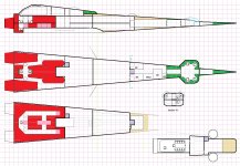
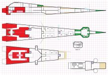
Yes, extremely awkward.The passenger airlock from the boat and the half-height access to the marine bilges are a bit awkward?
Not bad. Not sure I want to force passengers to enter though the troop quarters though.Make the cargo hold fully one and a half deck high, move the bulkhead back a square to get the passenger airlock in the passenger area (not the cargo hold)?
Some potential there.Make a full height stairs from the passenger airlock down to the marine bilges, make the airlock between the crew deck and the midwall cargo hold into a notch for the stairs (perhaps with an emergency hatch)?
That's kind of the solution I declined to use for the foredeck/mid-decks split.Or even widen the stairs and have up and down stairs side-by-side?
I wastes a lot of space.That's kind of the solution I declined to use for the foredeck/mid-decks split.

You're thinking in two dimensions.What about port/starboard airlock(s) for boarding actions in support of customs inspections?
The deck offset is to recover the space in the double-height section of the gooseneck and back into the space between the wings.My take on that picture is there is only 1 central deck, there is an upper and launch docking area. At most 3 decks stacked on top of each other. There is no need ro offset decks.
Ok, maybe not. Remember, the wings are 3m thick at the root where the ship's boat's cargo door aligns. If I move a chunk of Jump Drive over, there's room in the wing to slide a 4.5m wide chunk of cargo sideways out the door with clever use of a two-way loading ramp/platform. Maybe. I'll have to sketch it out, and I'll end up matching it on the other side.I'm considering using the lower half of the lower deck's cargo bay (that is, the area that surrounds the ship's boat intrusion) for fuel to give the cargo bay a flat load floor, and providing a crawl-space through it to provide access to the drive bay that bypasses the cargo hold.
Yeah, no.Or maybe I'm just getting too clever. I'll sketch and see...

There's a fundamental fallacy at work here ... that 2D artists are AWESOME aerospace engineers.I'm not sure that a 4.5m wing root thickness is plausible; this will take a little measuring and math.
I think you're painting yourself into a corner.Or maybe I'm just getting too clever. I'll sketch and see...
To be fair, as long as everything else about the lift surface scales, it should be fine.I'm not sure that a 4.5m wing root thickness is plausible; this will take a little measuring and math.
I honestly have no problem with this. "Looks cool" should be line item number 1 of the "design evaluation" step. "applicability to role", "cost", etc. are all secondary.They draw whatever "looks good/looks cool" and sell it for publication.
Gravity control/engineering solves SO MANY problems in aerospace ... especially when combined with heaping helpings of fusion power.But, this is Sci Fi in the Far Future, and having megawatts of power on hand and at the ready solves many problems compared to today where the goal is to reduce power as much as practical.
Neither do I, honestly.I honestly have no problem with this. "Looks cool" should be line item number 1 of the "design evaluation" step. "applicability to role", "cost", etc. are all secondary.
Oh, it's obvious the design isn't informed by actual aerodynamics or much consideration for engineering -- it's art.There's a fundamental fallacy at work here ... that 2D artists are AWESOME aerospace engineers.
They're not.
They draw whatever "looks good/looks cool" and sell it for publication.
Trying to make a 3D deck plan a PERFECT MATCH to a 2D artist's impression is a Fool's Errand.
In other words, you can be inspired by the appearance of the 2D art for your deck plans, but relying on that 2D art to constrain every aspect of your deck plans is a first principles mistake.
Getting "close enough" works just fine ... see the LBB S7 Scout/Courier as an example of the deck plan not being a "perfect match" for the 2D perspective drawn artwork.
I think you're painting yourself into a corner.