There's a reason for that.

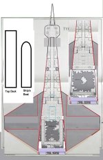
I'm becoming increasingly convinced I ought to shove the whole thing outside the hull and add about 1.5m depth worth of docking adapter/fairing under the lower deck on either side of the boat (in other words, just drop the boat 1.5m and fill in around it).
That would be my recommendation too.
Docking adapter/fairing, fuel and life support couplings, extendable manipulator arm(s) for the "last few meters" capture and control of docking procedures ... you know the drill.
Having a "through the ship from stem to stern" single deck is very much a superior option ... as would a
Modular Cutter with a G-Carrier berthed within it and a smaller cargo bay as a result (you lose about 12 tons of cargo capacity in the exchange). Although, if you move the troop barracks and low berths into the
Modular Cutter Module (5 staterooms plus 4 low berths plus 8 ton G-Carrier equals 30 tons!) you would actually offset the loss in cargo capacity sufficiently to be able to have
a second Modular Cutter Module configured purely for cargo as a reserve option that the
Modular Cutter could mobilize for transfers without needing to bring the entire ship along, increasing operational flexibility even more. Note that this "multiple modules" potential was the first thing that brought to mind my
LSP Clipper and
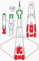
Five Sisters Clipper designs as commercial merchant/courier variants using the exact same form factor (400 ton needle/wedge hull) and standard drives, where the intent was to turn the basic idea into a profitable commerce ship. By contrast, my
Patrol Corvette evolution was an attempt to "march down the technology curve" from TL=10+ into better drive performance as a policing/pirate hunter and customs enforcement ship (so more of a paramilitary rather than civilian evolution).
Of course, from a "where do the puzzle pieces go?" perspective, it makes the most sense for the cargo bay to be on the ventral lower deck (for easy loading/unloading while landed in a gravity well without requiring a crane infrastructure) and any subordinate craft to be on the dorsal upper deck "leeward" of any atmospheric entry forces. By segregating things that way, you don't need to go "through the small craft AND ship" to reach the cargo bay from the exterior.
The problem with doing that in deck plans is that you're then deviating further away from the 2D design aesthetic of the original artwork (making the result "less perfect" as a deck plan in harmony with the art). Depending on how much "fealty" you feel is constraining you towards the impulse of "Must. Match. Art!" will determine how much leeway you feel comfortable with giving yourself.
My philosophy is that what is detailed in LBB2.81 would
definitely be a first draft version of the class, but that later iterations once operational experience is gained with the class in service could EASILY result in later updates and improvements and changes being made to the class (kind of like block changes in aerospace fighter designs over time). In other words, the LBB2.81 version could easily be a "centuries out of date" Block 1 version ... with later updates (Block 2+) and evolution of the design happening over time to improve the capabilities and make a "better ship" evolution after operational experience (and feedback) is gained from having the Block 1 in service.
Don't think of the Type-T information we've been given as the definitive "last word" on the subject in which Nothing Ever Changes EVER after the one and done. Instead, start thinking in terms of a "lineage" of starships, each iterating on the shortcomings of the previous generation and making subtle improvements around the basic form factor to yield an overall superior systems integration/update over time.
Think in terms of an evolving continuity ... rather than a static stasis ... and you'll be a lot happier with the results.
Or to put it another way ...

Some people manage by the book.
Even though they don't know who wrote the book
or even what book. 


")