• Welcome to the new COTI server. We've moved the Citizens to a new server. Please let us know in the COTI Website issue forum if you find any problems.

CT Only: Fixing the Type T Deck Plans?

Whenever you can recreate the ship someone else create to within a few squares, (tons or visually) you know you're doing the right thing. The first ship for me was the Gazelle and it set the standards for all my rooms and designs since them. I think you did a great job.
 
Whenever you can recreate the ship someone else create to within a few squares, (tons or visually) you know you're doing the right thing. The first ship for me was the Gazelle and it set the standards for all my rooms and designs since them. I think you did a great job.
I was motivated by the realization that the cover illustration came from a different set of deck plans than what got published. At first, I thought it was just minor changes... Once I realized that the original plans got lost along the way, I felt compelled to bring them back as best I could.

Thank you.
 
One of the ships, I called the Havara Class Freighter came about in the exact same fashion.

Many moons ago, I was traversing the Planetary Information System (PIS) when I can across a now defunct site where the creator posted a 3D image of the Defiant from DS9 and touted it as his free trader but had no deck plans posted. I said to myself, 'Psst, I can do better than that!" Thus, the Havara Class was born.

I'm working on another project for the New Traveller Art Forum which will lead into me posting my freighter designs, so hold your little horses and it will be up soon (I hope?)
 
Do you know how many revisisions I have on some of my ships or how many years I've been reworking the same design? The Havara has at least 3 and has been under construction and or modification since 8-31-2003. One verision was posted way back in 2015 so, post what you got and we'll go from there :). PS: we always tinker with our designs from the day they were born :unsure:.
 
Last edited:
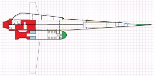
Side view. Those tip sails (particularly the lower ones) are bigger than I thought.

The hinge point for the lower fins has to be slightly below the wing surface so they'll clear the ship's boat (and each other!) when retracted.

Might be able to put landing gear there, somehow. Or not.

Note that the Ship's Boat is shown docked sideways, as it would be for cargo transfer. It can also dock in a normal orientation -- I've added a ceiling hatch located between its airlock and lavatory (this is a minor modification and should be fairly cheap and easy to arrange).

Also, in reference to feedback, there is a hatch from the loading bay (the space ahead of the GCarrier, with the opening in the roof) into the drive bay. It doesn't show in this slice because it's off-center to the far side.
Side View.jpg
 
Last edited:
Personal taste here: Blunt the nose back to the original drawing. It will give you more room for the avionics and computer plus, soften the underbelly slightly. This will also allow the area necessary for the landing gear and mooring claps for the launch. The other point here is the upper hatch (round hatch or hatch in roof of launch) square it, so more cargo can go through it. Take a look at my Gigs in the Gazelle Study to see what I finally mean.

Finally, if you have a hatch in the roof, there is no need to turn the launch on it's side to unload cargo. Both the side airlock and that hatch serve the same purpose. You're not going to fit anything but boxes though both anyhow. A 1 Ton Cargo container is not going to fit through the airlock door.

Advise: Short and broaden the winglets to just below the Launch. You can store one set of landing gear in there. Plus, if the you're running low on fuel or need extra fuel to refuel all those vehicles on board, the winglets can act as an extra fuel tank. In the Gull Class Survey Vessel, the long lower winglets serve that purpose, thou, I never stated it or showed it. Making the launch more aerodynamic seem a good idea to. Use a gig from the Gazelle or Fiery, maybe the launch from Subsidized Merchant. I believe every depicting I've looked at has refueling scoops and it would help in atmospheric reentry.

Question: Do you still have a Ship's Boat in the design or did you remove it in place of the Launch?

The hard part's are over and now the fun begins. Make the design you're own since, the publisher didn't get it right the first time around. AND if you're off a few tons, screw it.
 
One last thing (I promise!!!), the Turrets they are all on the top of the vessel. From a military stand point, that insane in a 3D environment. If you can, move at least 2 of them to the belly. So, an enemy ship doesn't get underneath you and blast you out of space plus, they can be used as ground defense when landed.
 
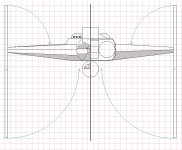
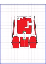
Front and rear split view. I think the forward (laser) turrets are hidden by the flight deck bubbles, but am not sure. In any case, they're not shown...

Blue arcs show tip fin folding paths.

End Views.jpg
 
Last edited:
Personal taste here: Blunt the nose back to the original drawing. It will give you more room for the avionics and computer plus, soften the underbelly slightly.
I'm trying to replicate the illustration (see page one of this thread) even if it's awkward. Honestly, I'm not quite sure the flight deck and its domes actually work out geometrically -- but they're there, so I'll let it go. The computer is just aft of the bridge; there's a walkway through it. The "rest of the bridge" is in the crawlspace forward of the missile turrets that's ahead of the missile magazine, and as antennae in the wingtip fins.

I don't know what the fins were meant to be, other than artistic flair. They don't make aerodynamic sense, even if the rest of the ship could work.* They're either antenna housings or have something to do with the Jump Drive, and nothing in canon suggests the latter. So, that's where the antennae are, and that's bridge tonnage.

Clean sheet design? I'd replace the deck and domes with bubble canopies, and if needed add an inverted V-tail instead of the tip fins.
This will also allow the area necessary for the landing gear and mooring claps for the launch. The other point here is the upper hatch (round hatch or hatch in roof of launch) square it, so more cargo can go through it. Take a look at my Gigs in the Gazelle Study to see what I finally mean.
The hatch in the roof is solely for personnel access. It's there so the ship's boat can dock with its deck at the same orientation as that of the parent ship for convenience (personnel don't have to re-orient on exit, and more important, it saves having to explain the process to players...)
Finally, if you have a hatch in the roof, there is no need to turn the launch on it's side to unload cargo. Both the side airlock and that hatch serve the same purpose. You're not going to fit anything but boxes though both anyhow. A 1 Ton Cargo container is not going to fit through the airlock door.
If you're transferring cargo, rotate the Ship's boat in the docking clamps to pass cargo out through the big door, as shown. You'll probably want to turn off the gravity first! It can't have both a side and roof hatch of that size (they'd interfere), and the standard one has it on the side.

By moving the freight elevator up out of the way and removing/retracting the outlined area on the middle deck floor, it's possible to get a block of cargo that exactly fills the ship's boat's cargo hold (4.5m wide, 6m long, 3m tall) into the ship's cargo hold. Slide it in, tip it over, and slide it onto whichever deck you want to store it on.
Advise: Short and broaden the winglets to just below the Launch. You can store one set of landing gear in there. Plus, if the you're running low on fuel or need extra fuel to refuel all those vehicles on board, the winglets can act as an extra fuel tank.
Again, I'm trying to replicate the illustration -- If I were starting with a clean sheet, I wouldn't even have them! But they're there, so I have to make them work.
In the Gull Class Survey Vessel, the long lower winglets serve that purpose, thou, I never stated it or showed it. Making the launch more aerodynamic seem a good idea to. Use a gig from the Gazelle or Fiery, maybe the launch from Subsidized Merchant. I believe every depicting I've looked at has refueling scoops and it would help in atmospheric reentry.

Question: Do you still have a Ship's Boat in the design or did you remove it in place of the Launch?
It's a ship's boat from S7: Traders and Gunboats, with only the extra personnel hatch added.
The hard part's are over and now the fun begins. Make the design you're own since, the publisher didn't get it right the first time around. AND if you're off a few tons, screw it.
The thing is, the publisher got it right for what they were doing: making a set of plans that could be printed and produced. What they got wrong was that the plans weren't for the ship pictured on the box...

I'm drawing the plans for the ship pictured on the box. :)

I suppose the flip side of it is to then go on to draw pictures of the ship that the FASA deck plans describe, except that I'm pretty sure it wouldn't look nearly as good...
---------------------
* First, they aren't far enough aft of the center of mass to provide lateral stability -- no moment arm. Second, having the lower fins longer than the top ones induces adverse roll with yaw (point the nose right and the ship will roll to the left, which is destabilizing). Third, they're far too tall to just be end plates, and the wings are too sharply tapered to be generating much lift out there at the tips anyhow.
(I used to design radio controlled model airplanes, so this sort of thing bothers me more than it would most people.)
 
Last edited:
One last thing (I promise!!!), the Turrets they are all on the top of the vessel. From a military stand point, that insane in a 3D environment. If you can, move at least 2 of them to the belly. So, an enemy ship doesn't get underneath you and blast you out of space plus, they can be used as ground defense when landed.
Yeah. That's not at all where I'd put them if I was starting from scratch.

In fairness, it's less important than it might appear, since space combat is well beyond visual range and orientation doesn't really matter. Feels wrong, though.
 
I don't know what the fins were meant to be, other than artistic flair. They don't make aerodynamic sense, even if the rest of the ship could work.* They're either antenna housings or have something to do with the Jump Drive, and nothing in canon suggests the latter. So, that's where the antennae are, and that's bridge tonnage.
They aren't aerodynamic features, since they're effectively asymmetric "wings" oriented at right angles to the fuselage.

Best explanation that I have for them is that they're vacuum only heat radiators.
They're all surface area with little volume and they only "deploy" into their vertical position while in vacuum to help control thermal management of the ship. Standard drive power plants are "wasteful" on fuel consumption (LBB2.81 vs LBB5.80 fuel formula difference) because they need to rely on use of (more) fuel for coolant in smaller ship hulls for the same drive letter (less volume/area to dissipate heat). However, dumping heat through use of extra fuel is merely one method of thermal management ... the other would be large radiator surface areas.

Furthermore, by placing the thermal radiator areas as far away from the main hull as possible you're helping to ensure that any incoming thermal lock on weaponry will inflict damage as far away from the fuselage (and thus, crew) as can be reasonably managed.

As soon as you stop thinking of those gigantic winglets as aerodynamic surfaces for controlling atmospheric flight and convert over to the notion of vacuum radiator for mitigating thermal heat build up in the liquid hydrogen fuel (that you do NOT want to allow to reach boiling point and explosively rupture the fuel tanks!) the design starts looking more plausible, if not quite almost reasonable.
Tip sails can improve wings' lift characteristics. They're about 2/3 as effective (when reasonably sized) as simply adding an equivalent amoutn of wingspan. They're used on jetliners and other transport aircraft because excessive wingspan increases the space needed for parking.

The problem is that if they're radiators, they're probably necessary. The reason this is a problem is that if they were a necessary feature, more ships would have them -- and they don't.

I see them as a housing for phased dual antennae (or the far future equivalent). Yeah, it's an interstellar cop car with dual CB whips. :)
 
Last edited:
Antennae or radiator or both, are good ideas to. They could also be giant sensor suites 'looking' for those ships trying to avoid poor olde smokey as they try to smuggle that Vegan Ale...
 
Next up: 1/2"=1.5m deck plans, in pieces.

It almost works on 8.5x11" sheets, oriented lengthwise. It would work if I could print in the margins -- or if I accept that I'm not getting the tail end of the drives that stick out the back, onto the maps.

... or if I had a tractor-feed printer that took accordion-fold paper. (I do, but it's in storage somewhere... and that's not a generally available solution anyhow.)

This could take a while, since I don't think it'll zoom to double the original size all that cleanly despite starting with *.bmp files so I'll have to re-draw everything. Easy work, but tedious.
 
The reason this is a problem is that if they were a necessary feature, more ships would have them -- and they don't.
Different trips with different ships (or words to that effect).

Do not take the lack of a "common visual language" among all Traveller ship art as being some kind of failing or indication that "well, nobody else is doing that, so..." is the exclusive only possible interpretation. Not all ships are going to look exactly alike or be engineered exactly the same way.

Think of it this way.
Other ships don't have those features because they were designed differently so as to not need them.

Kind of like how some aircraft have canards and others don't.
Not every aircraft needs (or wants) canards ... but on those that do, they're a useful design feature, rather than something "invalidated" by the lack of canards on (lots of) other aircraft types.

All I'm saying is that those gigantic winglets serve a purpose on the Type-T (aerodynamics, thermal management, sensor/communications avionics, rule of cool, take your pick...) and just because we don't see them "everywhere" on lots of other starship classes doesn't ipso facto pigeon hole them into a single rationale possible when we try to puzzle out (with our limited understanding) why they might take the form that they do.

Also, it's perfectly possible for them to have more than one potential purpose, they don't have to be engineering exclusive to solving a singular problem. As Sandy Monroe likes to say about (real world) engineering, every single part/component in a design ought to be fulfilling at least 3 "jobs" at the same time to cut down on parts and waste. All parts ought to be multi-function, as opposed to exclusively single function.
 
Bits and Pieces, hacked version.
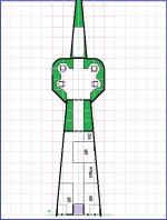
Bridge/foredeck, on 8.5x11" (cropped to 8x10.5" for printing).
Original 1/4"=1.5m scaled up 2x for 1/2"=1.5m. Not pretty, not final -- just a demo, seeking feedback.

Computer is immediately aft of the flight deck.

Note that the outermost two hatches on the aft bulkhead lead to the laser turrets, located in the space above the aft two staterooms . The turrets do not impinge on the staterooms below them, and those hatches do not connect to the staterooms.

The innermost (starboard side) hatch designation on that bulkhead represents two vertically-stacked hatches. The upper of the two leads to the common area on the upper mid-deck, and exits there near floor level. The lower of the two leads to the portside barracks on the lower mid-deck, and exits there near the ceiling. Both hatches are remotely locked unless the elevator is inoperative.

Nose Demo.jpg
 
Last edited:
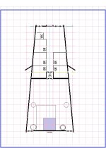
Upper Mid-Deck (aft flight crew quarters, upper cargo deck). Again, low-res 1/2"=1.5m for printing on 8.5x11".

Note that the outermost two hatches on the forward firewall lead to the laser turrets, located in the space above the aft two staterooms in the Bridge/Foredeck plans. The turrets do not impinge on the staterooms below them, and there is no access to them from the staterooms.

The inboard portside hatch adjacent to the elevator at floor level connects to the starboard aft stateroom, and is remotely locked unless the elevator is inoperative.

The ceiling hatch near the airlock to the cargo hold leads to the electronics bay and missile magazine in the attic (top deck). This is part of a pathway from the aft flight crew deck to the engine bay that bypasses the cargo hold.

The ceiling iris valves port and starboard in the middle of the cargo hold lead to the missile turrets above.

The floor iris valves port and starboard at the aft end of the cargo hold lead to the lower cargo deck. There is only one ceiling iris valve here, on the starboard side -- it connects to the loading bay in the attic (top deck).

The lavender 3m x 3m square at the aft end of the cargo hold is a freight elevator.

The grey outlined area adjacent to it is a section of the deck that can be retracted/removed to provide clearance for positioning oversized cargo delivered by the Ship's Boat.
Top Mid Demo.jpg
 
Last edited:
Upper Drive Bay. Low-res, 1/2"=1.5m, for printing on 8.5x11" sheets. Demo, not final.
It's immediately aft of the Upper Mid-Deck.

Ceiling hatch port side leads to the loading bay in the attic. This is part of a pathway to the aft (upper) flight crew quarters deck through the missile magazine and electronics bay that bypasses the cargo hold.

Aft blocks are the maneuver drive. Side blocks and center-aft chunk are jump drive elements. Big thing in the middle is the power plant. Floor iris valves port and starboard aft lead to the lower (jump drive) drive bay. There is an iris valve under the center of the power plant -- access to it is narrow and convoluted. It leads to an otherwise inaccessible part of the jump drive on the deck below.
Aft Upper Demo.jpg
 
Back
Top