• Welcome to the new COTI server. We've moved the Citizens to a new server. Please let us know in the COTI Website issue forum if you find any problems.

CT Only: Fixing the Type T Deck Plans?

But there are going to be times when direct Mark 1 Eyeball views of things would come in VERY handy. Things like docking with other craft (for insert reasons here), including maneuvering into and out of orbital berths (cue Galaxy Quest scraping the ship on the way out of space dock) and of course, wilderness VTOL on terrestrial surfaces or on liquid lakes/oceans.
This is why the seats swivel (and perhaps are gimballed), and there's nothing (nothing solid -- just the holographic heads-up display projections) in front of the seats in the bubble. Basically, I see the domes as a pair of wrap-around bubble canopies, each with one seat "suspended in mid-air" in the middle of it (they're on struts, but whatever).

The center-forward seat pivots to face aft (and face the other two crewmembers up front). It also can be placed in the full upright position with the tray table stowed, then rotated to face either port or starboard, and finally slid backward (that it, to the opposite side from where it's facing) to provide clearance to get to the access panel under the dashboard.
 
Last edited:
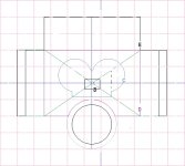
Recovered the transverse section bounding boxes file. Turns out I just forgot what I'd named it, combined with the website not liking *.bmp images.
Here you go:

Front Boxes Plans 2.jpg

B is just slightly ahead of the flight deck.
C is through the flight deck
D is at the wing leading edge/top deck front edge
E is at point of maximum height

These are the outermost points justifiable by the plan and the illustration.
A lot of corner-beveling is going to happen here...
 
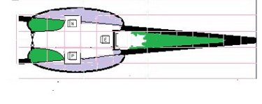
And a (nastily bodged) flight deck layout.
Flight deck.jpg
Purple indicates there's no floor in that area -- it's the bubble canopies.
*jpg artifacting screwed up my ability to fill that area cleanly.
The Pilot and Navigator seats should be about half a square forward, but I stuck with the grid layout for simplicity.
 
Last edited:
And a (nastily bodged) flight deck layout.
Flight deck.jpg
I think you're making a mistake with your bridge bubble proportions.
You're failing to "unskew" the perspective of seeing the ship mostly in profile, rather than in a direct top down orientation.
Look:

index.php


SrFEmSW.png
 
Agreed that the bubbles aren't quite what the drawing shows (I think I cribbed the idea from @magmagmag, credit where due).

What's weird is they seem to be in a sort of frame that doesn't exactly conform to the shape of the bubbles.

This drawing captures the "frame" nicely, but I think they've overdone the centerline window because it just doesn't look like the fuselage is that tall that far forward:
Nose Snip.JPG
 
What's weird is they seem to be in a sort of frame that doesn't exactly conform to the shape of the bubbles.
It's not "weird" ... it just means that they aren't arranged in quite the way you were assuming they were.
Like I said, there's a "belt of bulkhead" wrapped around the outside of them, holding them in place against the sides of the bridge area.
 
On the other hand, is it really a belt, or is it the floor? That is, are there matching domes on the underside, or just flat-ish panels in shadow?
 
On the other hand, is it really a belt, or is it the floor? That is, are there matching domes on the underside, or just flat-ish panels in shadow?
I'm not seeing any underside bubble space in this image.
Do you?

So "bulkhead floor" might be more accurate ... however, the point still stands. The bubbles are not "free floating extensions" outboard of the fuselage. If anything, they're more like canards with an elongated dome on top (which would be shielded from direct impingement with atmosphere during an aerobraking maneuver using a slight pitch up angle of attack directing most atmospheric friction heating towards the ventral underside leaving dorsal parts of the ship in the "shadow" of the aerobraking friction plasma heating).
 
index.php

That center section looks like it could hold another pilot station? It's raised above the outward canopies and appears to have a viewport as well from the shading? Maybe, the canopies are positions for other crewmembers with Bridge duties and the pilot sits in the center position?
 
That center section looks like it could hold another pilot station? It's raised above the outward canopies and appears to have a viewport as well from the shading? Maybe, the canopies are positions for other crewmembers with Bridge duties and the pilot sits in the center position?
How about this notion then?

Start with the Type-S Scout/Courier bridge layout from LBB S7.

DM5uKOE.png


Those bulges around the bridge?
That's where the ship's computer equipment goes ... so it's "adjacent" (in this case, wrapped around) the bridge.

Additionally, how many crew members are expected to be "in attendance" on the bridge with permanent duty stations there?
Pilot: yes
Navigator: yes
Chief Engineer: not full time
Other Engineers: probably not
Purser: no
Steward: no
Medic: no
Chief Gunner: not full time
Other Gunners: probably not

So realistically, you're looking at having 2 full time bridge officer workstations and 2 "part time" bridge officer workstations that aren't always manned (but which probably are manned during Red Alert™/General Quarters situations).

Even if you take the precedent of the Scout/Courier bridge and make it into an elongated octagon shape (2 stations angled forwards, 2 stations angled rear) you still don't have an adequate explanation for what those bubbles abeam of the bridge actually are (or are for).

cBEjy7f.png


This would be my impression of the minimum size for a 4 workstation bridge that occupies a total of 10 deck squares (5 tons displacement).
 
Not sure there's really room for people in the domes. If so, it's cozy.
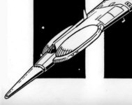
(Based on the FASA artwork.)
Nose Side.jpg
Which is why I prefer to implement them as bubble canopies with one crew member in each canopy.
 
Last edited:
I think the basic visual idea is that they're the "eyes" of the "mosquito" that the ship vaguely resembles. Functionally? They just crammed seats in there because that's nominally the flight deck and it needs seats. It's close enough, I suppose, but if the domes aren't transparent (and in the artwork, they don't really seem to be, since the "windshield" is colored differently) there's no good reason for them to be that shape.
 
Last edited:
The easy way out is to just keep the flight deck layout from the deck plans. I don't really like it, but it's there and I'll have my hands full rearranging everything else.

The next step is working out the two/three-deck layout in the aft section -- how far forward of the wing it stays as two decks, mostly.
 
It's a full 3m tall at the wing leading edge/start of the top hump.

It's two decks tall up to the panel (exterior) break forward of the turrets,

It's about 2.8m thick there, and forward of that point the ceiling or floor would be impacted by the hull slope.

Time to start the math and get to drawing.
 
Last edited:
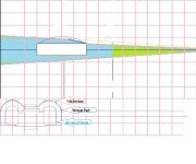
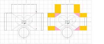
And this is what happens when you bevel off the corners of the forepart of the hull.
The pink area is what got clipped at the base (section at the wing leading edge).
The orange area is what gets clipped because the pink area got clipped. Note that this leaves only a 4.5m wide "attic"!

Still using the close-in double-bubble flight deck outline; that'll change.

Excluding the bulge for the flight deck, the forepart of the hull is 49Td.
FD Section Plans 4.jpg
 
Seems to me that the lower deck forward of the wing leading edge is going to lose a bit of floor space to the beveling of the hull corners, and there'll be low ceilings in the outer edges of the upper deck. I think most of the support stuff goes into the ceiling of the top deck and floor of the bottom deck, so the floor of the upper deck comes out as thin as possible. I suspect I'll just have some spots where the crew will have to watch their step as the deck height changes by about 15-30cm.

I'm having trouble visualizing where conduits are supposed to go, though. They'll stick out in places...

The aft is slightly more complex...
While the "attic" is only 4.5m wide, there's a fillet between it and the outer edge of the top of the middle deck, which continues expanding almost all the way aft. So it's only 4.5m wide at its base at the wing leading edge. There'll be several tons in the fillets, not that they'll be useful for anything but fuel and lockers for nitnoid stuff.
 
Last edited:
Now, to do the geometry and the math.
The two main decks are a tapered rhombus in plan view, and of constant 6m thickness (mostly).
I think I can do the whole thing by multiplying the mean cross section by the length, then carving out the vertical taper at the aft end. Won't be exact, but doing it exactly is going to take more measurements and math than I want to get into right now.

The attic can be approximated as half an ellipse in side view, multiplied by the 4.5m width. Or I could try to do it piecewise but that's too much like work.

The fillets between the attic and the middle deck... Hmmn. Might just guess at it, but it's probably not impossible to work it out geometrically.

Whatever isn't in the main hull goes into the wings. With luck it'll come out somewhere in the ballpark of the required 240Td (ex fuel), but I bet the corner-clipping knocks it too far down to be plausible. We'll see.

Then, just "wing it" for component placement. (this block of staterooms are X tons, this space is about X tons -- draw it up and don't worry about precisely how big each room is...)
 
Back
Top